For this Thursday, we had our usual meeting, where each of us recounted to one another what we had accomplished since last time, what issues we encountered, and what we planned to do next. Using Trello, we browsed through the first sprint, discussing the various tasks and their status, making sure we had some idea where we were with each one. Once we were satisfied, we decided to proceed to the second sprint. Below is an overview of the progress for each discipline.
Mechanical department
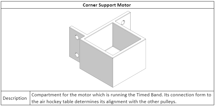
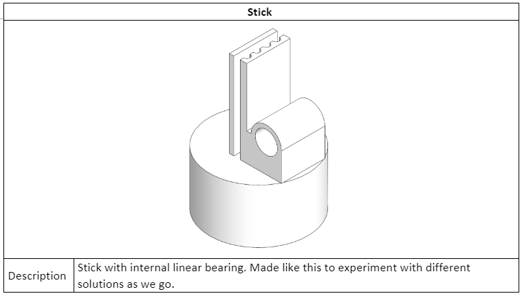
The last two weeks have primarily involved further improving the design of the air hockey board and creating an initial design for the stick system. We wanted to be able to start creating a 1st prototype already on Thursday 12. Sept, but because we lack some of the parts needed, as well as uncertain delivery times and an unknown budget from the lecturers, this was pushed back one week. Below you can see the newest version of the 3D model for the prototype of the stick system. The prototype will be used for testing of the stick system. Where the orientation of the stick will be determined by two motors connected to each other with a timing belt. A visual representation of this will be applied to the blog at a later stage.
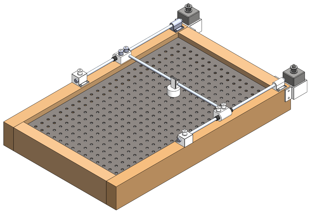
One of the changes to the actual board from last week is that we made the corners 90o rather than curved. This is because most air hockey tables are made this way and it will be simpler to calculate the discs path for the robot since there are less variables.
To reduce the time waiting for components and budget from the lecturers we made a budget list for components we need to buy. These components are shown with hyperlinks in the table below.
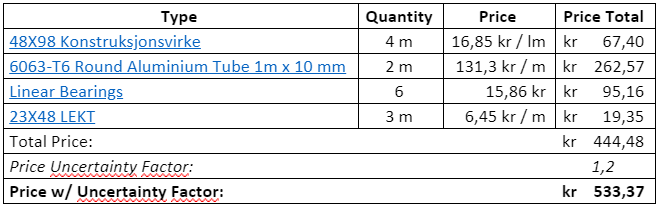
48X98 Konstruksjonsvirke
6063-T6 Round Aluminium Tube 1m x 10 mm
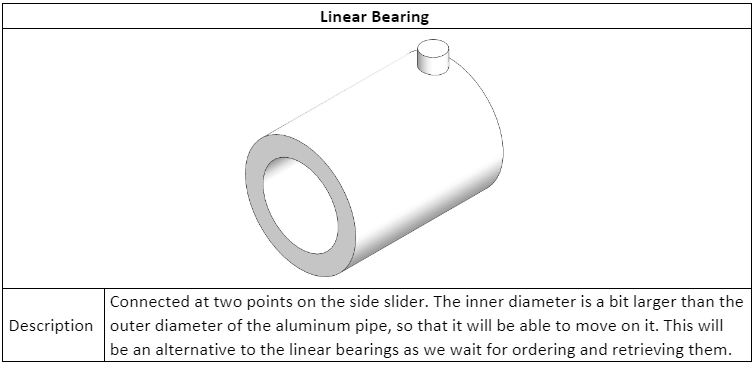
Linear Bearings
23X48 LEKT
These components were picked from more local distributors rather than cheapest price possible. This is because of the timeline of the project and the necessity of testing the functionality of the system sooner rather than later so that we ensure a functioning system at the end of the project period.
There was also a need to 3D print some components for the system. This is primarily for trialing and error testing at first and getting a functional system as soon as possible. It would be ideal to have as few components 3D printed as possible, but as of now for the prototype it is more time efficient. (PS. These are early models which is used to see the functionality of the system, each part will be modified throughout the project):
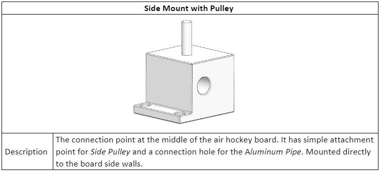
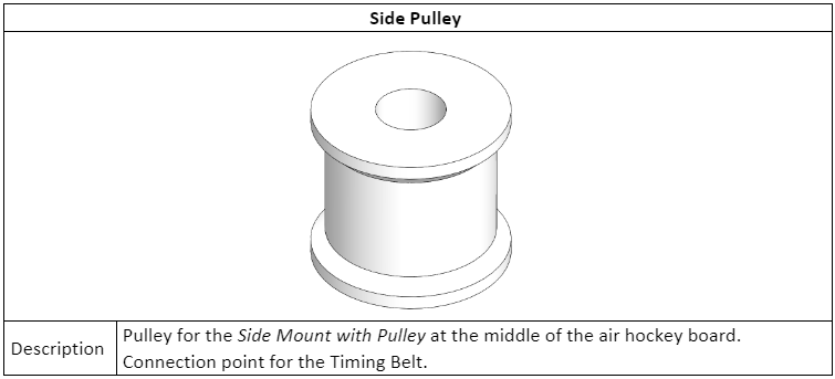
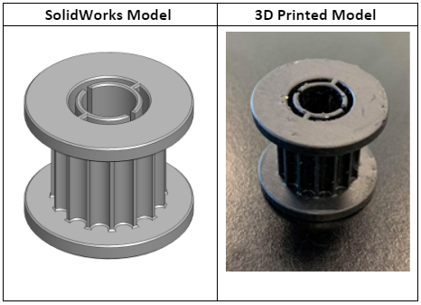
We have also been able to 3D print some components. Below you can see the pulleys that are designed for attachment to the motors both in SolidWorks and as a produced product.
Electrical department
In the last two weeks, the electrical engineering students have been experimenting with the stepper motors, so that we can get used to them and how they function. We encountered a lot of problems when trying to get them to work exactly as we want, especially because we are not very familiar with this type of motor. Furthermore, we are not entirely certain which driver we’re using to control them, as there doesn’t appear to be any model information or reference on the unit.
One day was spent trying to get the motor moving and learning how we had to wire the control circuit. Despite our best efforts, however, the circuit that we made wasn’t working, even though everything appeared to be in order. We tried to change it, looking for more examples and tutorials on the internet, but we didn’t find any good results. That day we left the school so disappointed.
The next week the computer science professor, Steven, who was also helping us the other day, informed us that he might have the solution: it was a problem with the intensity that we are applying to the coils of the motor. Furthermore, we realized that in addition to that problem, it turned out we’ve been configuring the micro steps switches incorrectly, as we were leaving them in the NC position (not connected)! Once we solved that problem, the motor finally begun responding as it should.
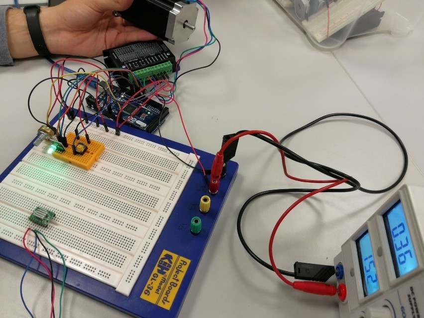
With the motor working, the next step was to get an idea of what speed we should move the motor to be able to create a competent computer opponent that could provide a good playing experience. For that task we decided to write a control code (in Arduino C) to vary the speed of the motor as we desired, after which we filmed the motor and a chronometer at slow-motion to be able to count how many rotations the motor is able to do in one second. Using this method, we got an approximation of the max rev/s of the motor. Furthermore, to be certain of the veracity of the past procedure we made some calculations about the relation of the steps that the motor does every second, and the number of steps needed to do one revolution. We got the following results:
1s / 300μs/stp = 3333,3 stp/s 3333,3stps / 400stp/rev = 8,3 rev/s
![[video-to-gif output image]](https://lh4.googleusercontent.com/dhWwnttsVNKC4x5fcbLrwI1KBaa-_iq-jdmGZacPJhehXpp2j8KhTlXHUvjJLymuuUdPAuIqJU6AgtB2BRMVIXJxOHfa88MbXk1x8oLrhW541AqvrRf-hAAbW9METQ)
These results are approximately the same that we get with our slow-motion experiment, and consequently, we concluded that it’s a good estimation of the real speed.
Computer department
We’ve made progress on the software side of things as well, where we’ve now started to watch and read tutorials about OpenCV, and experiment with the library. One minor issue we ran into early had to do with the camera’s interface with the raspberry pi; when we set it up initially, it worked fine, but when we restarted the raspberry pi, the camera would no longer work. We discovered this was because we had to manually load modules into the kernel, specifically the “bcm2835-4vl2” module, using the “modprobe” command. To avoid this issue later, we will likely have to create a script, so that it is loaded automatically every time.
As for the programming and usage of OpenCV itself, to begin with, we wanted to make the camera capable of detecting, and subsequently track any given object, like this:

The code for this that we found was fairly complex (relative to our experience), but we managed to make it work eventually, and we successfully detected a board marker, and partially managed to track it.
The issue we ran into here was that the FPS of the tracking was so low (2-5 fps) that it couldn’t properly keep track of the object. Consequently, when the object moved too fast, or was even partially obscured, the tracking was lost. First, we figured it could perhaps be because the GPU didn’t have enough memory, so we attempted to double it, to no avail. To get a better idea of memory usage and the like, we installed “htop”, which is a sort of system monitor that could serve our needs. Here, we discovered that a single core of the CPU was working at 100% capacity, whereas the other cores were maintaining around 10% capacity. Instead of beginning to look too deep into why this was the case, and how we might solve it, we decided instead to look into other methods we could use with OpenCV, such as color tracking.
We started out by making a simple Python program that tracked objects of blue color by defining the color range to be detected and masking the rest of the video image. This simple yet useful method helped us get a bit more familiar with OpenCV library and its basic functions.
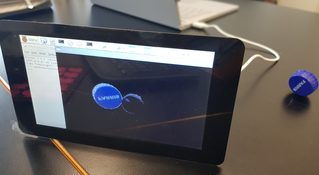
Our second Python-program detected the presence of a blue colored object using computer vision techniques as we did earlier, but this time it would also track the object’s movement in the video frames and draw its previous positions as it moves. We computed the contour of the object and drew it in on our frame by detecting contours in the mask and computing the enclosing circle and centroid since our object will be a disk.
![[video-to-gif output image]](https://lh6.googleusercontent.com/q_N6ZE146uDbb7isohjgdjmPxC-BwPDJTpy0ngI2nRz3MtLSUMs2qbEgiAADn57yRDi0kC0Vm7P8nZ51G9pGr7ayjFitIn2x003ONLD3bWBWFmu-KBeOd4b8OJh57JqVAGByDW5J)
We tried to evolve our program further by computing the centre (x, y) coordinates of the detected object and using it to compute the direction the object is moving in. The problem we faced is that the video feed from the pi-camera on the raspberry pi freezes on the first frame of our live video stream from the camera.
So, the question is: can we identify the source of this problem and fix it? With that being said, we experienced a lot of freezing in OS of the Raspberry Pi in general while working with it this week. This got us thinking that maybe this is a performance issue with the current Raspberry Pi. If it freezes at this point, will it be powerful enough for our object’s live position & movement tracking, as well as other computing when our program becomes more complex? We are using the Raspberry Pi 3 Model B (2015) currently, but we do have access to the Raspberry Pi 3 Model B+ (2017) that we could potentially program instead for better performance. But first, we could try resizing the image to a smaller resolution; there is no need for full HD (1080p).
Going forward, we want to deepen our understanding of the library, determine whether it’s necessary to use a newer Raspberry Pi, learn how to derive information from the tracking (e.g. angle, velocity), and test it with an actual disk and board.
Sources:
Car object tracking gif: https://www.pyimagesearch.com/2018/07/30/opencv-object-tracking/