We started week two with a meeting with all the group members where we got each other up to speed on what work we did individually since we last met. This consisted of mostly organizational work and simplified sketches and ideas of how we pictured the system to function.
In order to get a better idea of what sort of concrete objectives each discipline in our group would need to tackle, we used the system requirements we agreed on in week 1 to define a few preliminary assignments:
Electrical department:
- Verifying motor speed
- Make plan of how to power the system (schematic)
- Circuit for raspberry & arduino (movement)
- List of stuff that needs electricity
Computer department:
- Camera tracking of disc (python library: opencv)
- Algorithms (how fast to respond, angle)
- Program the raspberry (strategy, control, direction, how many steps, velocity, etc.)
- User interface (touch screen? Simple counter?)
- Timer
Mechanical department:
- Design / sketch of the hockey board
- Design & print of pulley for the motor
- Air pressure (fans to keep disc afloat)
- Sketch of disc retrieval system
General / administrative:
- Blog (documentation)
- Assign tasks to boards
Since our meeting on Thursday (29.09.2019), each of the disciplines have begun working on one or more of these assignments; what follows below is an overview of what each discipline has accomplished in the days following said meeting.
Mechanical department
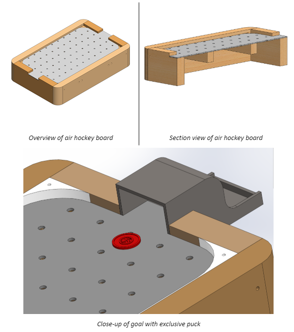
For this week the main assignment for the mechanical engineer student has been to identify the different mechanical parts that’s included overall in the automatic air hockey system, and then create a quick sketch of the air hockey table. The following image shows some of the parts for the board of the air hockey table and their relevant information:

Dimensions and pricing will be prioritized at a later stage of the project and has therefore not yet been addressed in the above table. The same has been done for:
- Puck ejection system
- Airflow system
- Stick system
The model sketch of the air hockey board is very simple at the moment, and is primarily just for the team to visualize the size and available area for the different components that is necessary for the whole system. It was also modelled to see where the support structures could be placed so that they wouldn’t block the air holes. The following figure show some overview pictures of the model sketch (earlier model):
Electrical department
Our electrical students’ main assignment was to figure out which motor was necessary to sufficiently drive the computer opponent’s stick with enough speed and precision to competently battle a human player. In order to find the most suitable motors for our system’s purpose we have looked at what types of electric motors that exists in the market. We found two types potentially capable of satisfying our needs: the DC motors and the stepper motors.
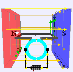
A DC Motor produces torque by the mechanical switching of the current. As shown on the image below, there is a permanent magnetic field produced by magnets in the stator. The current flow in the rotor winding produces a Lorentz force on the winding, represented by the green arrows. The motor ring is split in half, where each half is opposite poles, which creates a current flow that is reversed every half turn (180 degrees).
A stepper motor is an electromechanical device that converts a series of electrical impulses into discrete angular displacements, which means that it is capable of rotating a number of degrees (steps) to control. The stepper motor behaves in the same way as a digital-analog converter (D / A) and can be governed by analytical impulses of digital systems. This motor has the advantages of having accuracy and repeatability in terms of positioning.
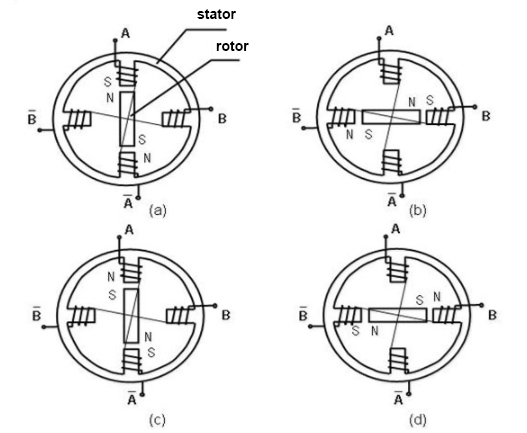
The stepper motors available on campus are bipolar, and therefore, to control them, the current in the winding must be reversed in order to reverse a magnetic pole. Consequently, the driving circuit is more complicated than the unipolar ones, typically with an H-bridge arrangement (however there are several off-the-shelf driver chips available to make this a simple affair).
Considering the motor availability at campus, as well as taking into consideration factors such as the size of the board, friction of the pulleys, and the potential velocity and attack angles of the disc, we have decided to proceed with two stepper motors. Specifically, the ones available at campus are the Nema 17/23 bipolar motors, with a single winding per phase. Further testing will be necessary to determine if these truly fill the criteria set by our requirements.
Computer department
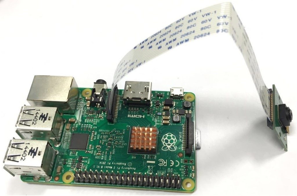
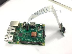
Our computer engineering students have made good progress with the raspberry pi. As explained in our previous blog post, we intend to use a raspberry pi and a camera module to facilitate the object tracking, which will allow us to track the disc on the board, and thereby allow the computer opponent to make the right decisions based on information such as angle, velocity, and so on.
We learned that to make this possible, one option was to use “OpenCV”; a library of programming functions to allow for real-time computer vision, and as a bonus, one of our group members were already familiar with this library. Furthermore, we also learned that this library was commonly used with python. Consequently, we have spent the majority of our time learning how to implement these on the raspberry pi, and have recently successfully done so, after some initial complications.
The biggest of these complications was the fact that the OpenCV library was not easily installed. To make it work, a number of dependencies had to be installed first, and even then, OpenCV had to be downloaded uncompiled, for then to be compiled by us (which takes a few hours). This crashed a couple of times, but after adjusting the number of cores the compiler was allowed to make use of, as well as increasing the swap size, it finally installed correctly.
That being said, the raspberry pi is not yet capable of object tracking; we have merely made the prerequisite software function, but we still need to decide on an algorithm (OpenCV has a few to choose from, depending on what you need), and subsequently program said algorithm in python.
Project Management
Project management has been considered further, and we now have a rough outline for the majority of the project, all the way up until November. The outline consists of 6 sprints, each lasting two weeks, where the closer sprints have more detailed tasks, and the sprints further away have more estimations / ideas for where we’d like to be at that point in time.
In our meeting on Thursday (29.09.2019) we made sure everyone was on the same page in terms of how and when to make use of Trello, to ensure the project progresses in a neat, orderly manner for each discipline. We made a test board where each group member can freely experiment to get used to the tool without fear of accidentally editing something they shouldn’t have.
Image Sources
Stepper motor image: https://www.ato.com/Content/Images/uploaded/stepper-motor-working-principle.jpg
Raspberry pi image:
https://neverbenever.files.wordpress.com/2015/05/pi_withpicam.jpg?w=300&h=225