Sokaina Cherkane 💻🦾
It’s coughing season🤧🎶But we won’t let that stop us!
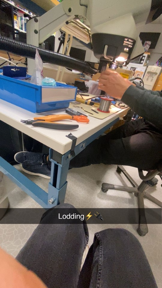
At the start of the week, I began by soldering a new OpenCM board under Steven’s supervision and with his assistance of course, which was both a valuable learning experience and enjoyable.
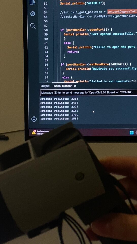
As shown in the attached picture, the code ran correctly, as verified in the Serial Monitor. However, the joint did not move in real life. I initially hypothesized that the issue could be due to unsynchronized code, a missing component, or a current-related problem.
Debugging the issue took time since the code showed no errors and appeared to be correctly configured. To rule out my suspicion of a current problem, I consulted Ivan, an electronic engineering student. He helped test the current setup, and we confirmed that the issue was not related to a current limit. Specifically, the servo’s current limit (which shuts off the servo when exceeded) was not the source of the problem.
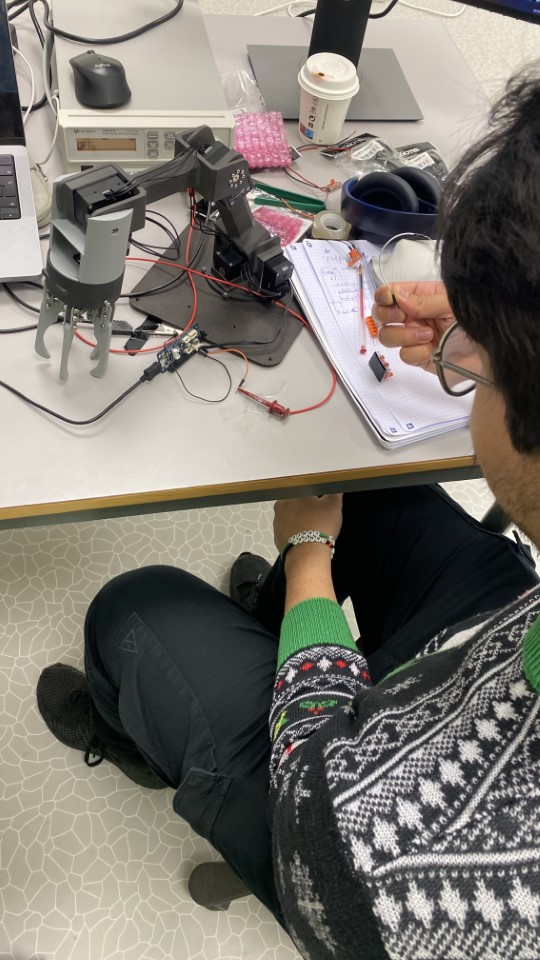
Debugging the issue took time since the code showed no errors and appeared to be correctly configured. To rule out my suspicion of a current problem, I consulted Ivan, an electronic engineering student. He helped test the current setup, and we confirmed that the issue was not related to a current limit. Specifically, the servo’s current limit (which shuts off the servo when exceeded) was not the source of the problem.
With current-related concerns eliminated, I redirected my focus to the code. Upon reviewing it carefully, I discovered that the third joint (DXL3) was set to move to an angle of 50, which was outside the operational range I had previously adjusted for the servo. Once I corrected the angle to fall within the allowable range, the joint finally moved—an exciting breakthrough! (See the attached picture.)
Following this success, I tested the other servos using the same approach. DXL4, DXL3, and DXL2 all moved correctly, but DXL1 did not respond. To investigate further, I swapped DXL1 with DXL0. As expected, the joint corresponding to DXL0 (now connected in place of DXL1) moved successfully, confirming that DXL1 was malfunctioning. Although the LED on DXL1 lit up, I suspect the internal motor driver or a related component is faulty. Despite this issue, we now have a partially functional robotic arm.
The next step is to synchronize all joints to work together so the arm can pick up a ball and place it back, as demonstrated in the attached video.
Hamsa Hashi 💻
Over the past two weeks, I have dedicated my time to troubleshooting the car to identify the underlying issues causing it to malfunction. The primary problem lies in the stepper motors controlling the wheels. While the wheels occasionally move, they frequently lose steps, leading to inconsistent performance. This has made diagnosing the issue particularly challenging and time-consuming. To approach the problem methodically, I decided to break the task into smaller, manageable steps. I tested each wheel individually, which demonstrated partial functionality, although still suboptimal. The more significant issue arises when all components are connected simultaneously, resulting in further complications.
To ensure a thorough investigation and proper testing of the system, resolving this issue has become my highest priority. To address it, I have decided to completely disassemble the car and rebuild it step by step, testing each component independently to identify the source of the problem. To support this process, I have written test code in both C and Python for each component—such as the stepper motors and joystick—so I can systematically determine where the issue lies.
By adopting this systematic and detailed approach, I aim to isolate and resolve the fault effectively. This process will allow me to build a more stable and reliable system, ensuring that the project can progress as planned.
Philip Dahl 🔋
The board from last week had been switched to get us as quickly back on track as possible, since I was needed elsewhere at the end of last week. Testing it this time, some other issue seemed to have risen, as uploading to Arduino gave errors and the led’s on it were suspiciously dim. As there were some battery issues that needed fixing, I took to troubleshooting the new board.
The first thing I discovered was a couple of short circuits between the terminals from the power supply. I assumed that this had been checked beforehand, but I should have made it clear and checked myself before connecting.
This was likely the main cause of the issues, though some other solder points needed adjustment as well. I replaced all the wires providing logic voltage to the circuit with “surface mounted” wires, which freed up a good amount of space. The process took quite some time as I wanted to be absolutely sure there were no short circuits, before attempting to upload again.
The dimmed led was now bright again and code could be uploaded, so I tried reconnecting the circuit. There was no immediate response from the steppers, but at least the power issue seemed to have been fixed.
Mikolaj Szczeblewski 🔋
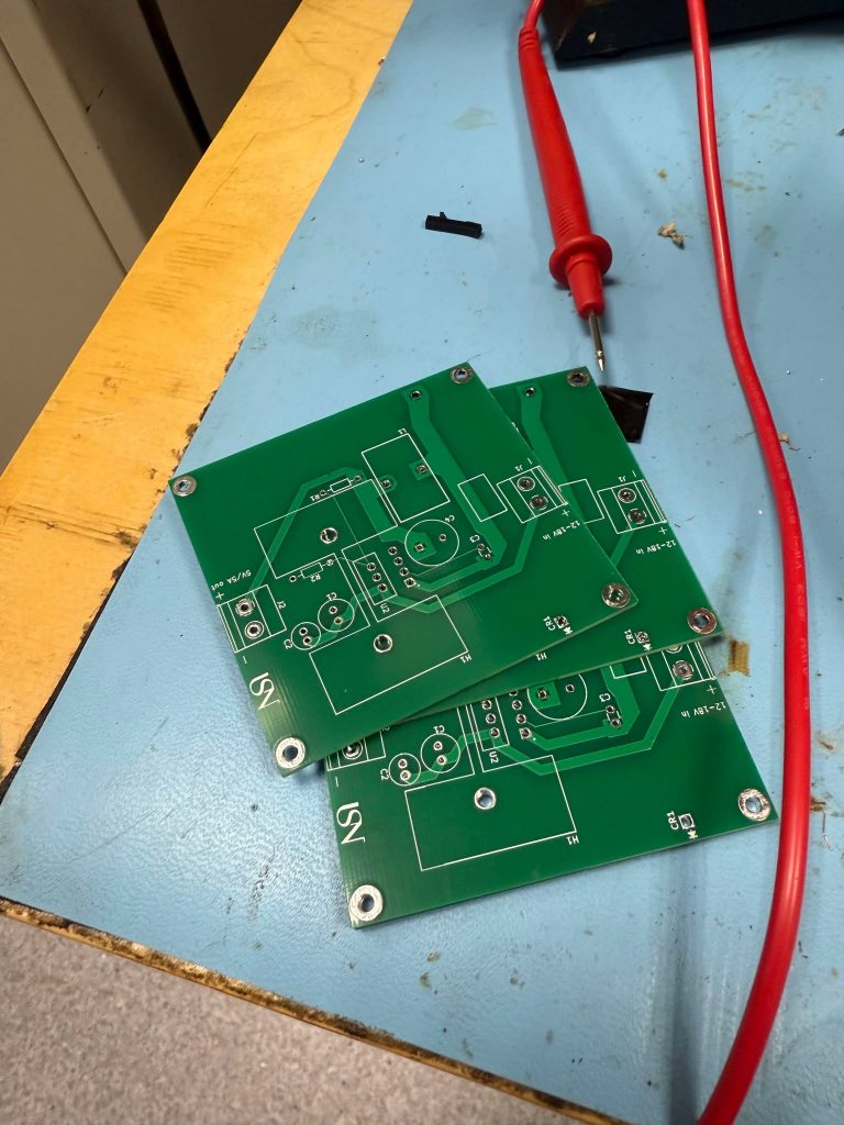
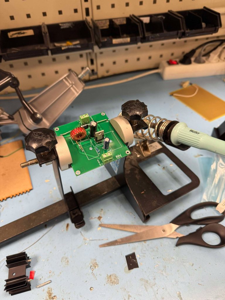
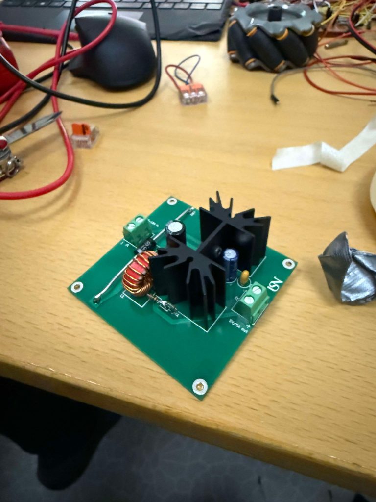
I’ve had to redo my design of the PCB and therefore it became a different result than my earlier iteration, I’ve added a ground plane and made the traces better suited for the current draw that it is supposed to work at. For this week as the very deadline approaches for our project. I’ve had to await the delivery of my PCB regulator, such that I can feed the necessary current and voltage to the remaining devices working at the 5V range. Keep in mind that our temporary solution for this was by using a power bank to keep the raspberry pi alive in the prototype – however we needed a more robust solution which can keep the whole prototype intact inside.
I’ve got my components earlier, also I’ve ordered standoffs and nut screws for the purpose of mounting all of the electronics in the prototype, the vehicle obviously would be vibrating violently under operation – and the electronics are therefore susceptible to damage and or / worst case scenario – short-circuits.
Ruben was absolutely incredible and helped me in visualizing where all of the electronics could lie inside the prototype, after deciding upon our solution, he drilled the holes and assembled the standoffs on the boards. Therefore, I really appreciate his cooperation in ensuring “aesthetics” in the prototype.
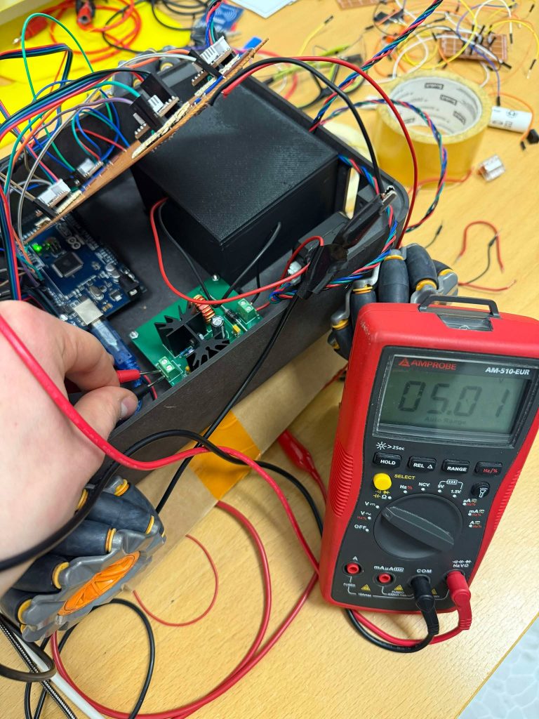
The regulator circuit arrived at the very last working day on the same week, and I’ve immediately soldered the components on it and mounted it the very same day with Ruben. And luckily, it worked!
Ruben Henriksen 🛠️
DONE:
This week I finally got to make the box for the battery and could figure out the placement for all the circuit boards. The battery box was made using a multibody part and 3D printed on my FDM printer. When the battery was finished I could then mount the stand-offs to the circuit boards and figure out where in the robot they could be placed. For this prototype I marked where the stand-off where and drilled holes manually, so some of the holes are a bit off but the 3D model is updated and I can laser cut a new plate with the correct holes. Lastly I made some brackets for the board with all the stepper motor drivers and mounted it to the roof, and the reason for this was to utilize the space within the robot more efficiently.
TO BE DONE:
All we need to do now is to assemble the whole robot