Sokaina Cherkane 💻
This week’s plan was to write a new C-code in the Arduino IDE to run directly through OpenCM. The goal was to control the servo motors, making the joints move one at a time, then two at a time, and eventually all three joints simultaneously, including the “hand” (the fourth servo motor).
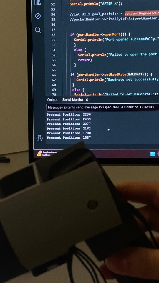
Unfortunately, my productivity on the project was lower this week due to prioritizing a presentation and a report that were due at the same time. However, I made some progress. I started working with DXL1, but encountered issues. As shown in the video, the arm’s position appeared to change according to the Serial Monitor, but no actual movement occurred.
+ video og bilde
Suspecting that the code was out of sync, I added additional print statements to the monitor to help identify and debug the issue. After several attempts, I discovered that the board had been damaged. It was unable to handle the current applied to the specific pins, resulting in a burnout (amateur issue😅). I had to pause progress for a couple of days while waiting to consult our professor for a replacement board.
Next week:
- “lodding” of openCM.
- Progress with the arm’s interactions.

Mikolaj Szczeblewski 🔋
For the time being we have a temporary solution for powering the prototype for testing, however we are waiting for the PCB to arrive, the parts required are also on the way and are here next week. Final assembly will take place next week as I can’t contribute much as of yet.
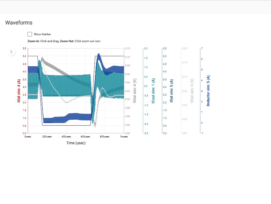
I’ve had difficulties in simulating the very final version of my circuit for the

regulator, however I’ve used Texas Instruments’ WEBENCH POWER DESIGNER tool, which is an incredibly strong program for simulating the circuit’s different transients, steady states, etc.
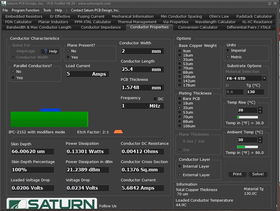
I’ve measured all the currents, and by the analysis – decided upon the tracing widths specifically where necessary. Additionally, I’ve used Saturn PCB Design’s calculator, which uses the IPC-2152 standard for determining current-carrying capacities in PCBs, KiCad has a different one which is a more generic one, but after reading on the forums and researching a bit, the majority recommends the first one mentioned.

PSpice model of the regulator gave me faulty simulations which I could not change despite changing parameters in an adjustable PSpice model of the component.
My plan for the circuit boards that we will be using – is to mount them in different places of the prototype, the OpenCM board ideally will have to be placed on either the arm or the top of the prototype platform. The rest of the boards will be placed inside, I’ve talked with the mechanical engineers and they will be helping me in finding suitable standoffs for them. It is important to have them since the prototype will be subject to vibration and everything should be mounted to avoid the entities flying around inside, and of course short-circuits may occur if this is not satisfied.
Philip Dahl 🔋
I finished up the board by soldering the remaining wires. Wherever the copper plates didn’t come off, half the wires refused to get any solder stuck to it, so it took way more time and effort than anticipated. It wasn’t the prettiest sight in the end, but luckily that is not my area of expertise, as long as it is functional. I used a multimeter to confirm that pins were connected where they should be before returning it to its rightful place in the base of the car.
When it was time to test, the steppers did not respond to controller inputs, and began moving at random. The result was tough. All the hours of back and forth soldering, for nothing to work. Hope at the moment was fleeting and I had to attend another issue, so my week’s work was concluded.
Side note
From week 6&7 I ran some simulations regarding a 12-5V step-down voltage converter. I realize, though a bit late, that this was a hasty and not well thought out decision. The battery pack made was not, in fact, 12V, making the simulations quite irrelevant. This was, as you say in chess, a real blunder. The time should have been spent on deciding on and acquiring the battery pack, and not what would come after.
Although this was a failure on my part, failure can be a wise teacher, if one is willing to learn. And dwelling on mistakes of the past will not help progression, so I digress.
Ruben Henriksen 🛠️
This week, I made the adapter for the camera, I had to make some small changes to the slots in the forward and aft plates so that the camera would fit in between. The camera adapter was printed in ABS since it is more ductile than PLA so it would be easier for the camera module to have a snug fit but also be easy to remove. The adapter is going to be glued in place so that the camera sits in the center of the robot.
TO BE DONE:
Next week I heard that the battery is finally finished so I shall make a box for it, and then I can figure out the placement for all the circuit boards.