Sokaina Cherkane 💻
This week, the primary objective was to test the control system to ensure the code functioned as intended. However, I encountered some challenges along the way, which were eventually resolved.
The servo motors in the robotic arm are controlled by the OpenCM9.04 board, which acts as the master controller. The plan was to connect my laptop (and eventually a Raspberry Pi) to an Arduino Mega 2560 board, which would then communicate with the OpenCM9.04. The code, written in Arduino IDE, would send tasks to the Arduino board, which would subsequently forward them to the OpenCM9.04. Although this process seemed straightforward in theory, it ended up being more time-consuming than anticipated, taking approximately two days to implement.
Thankfully, Philip suggested we use a method called “Voltage Divider” where we use a breadboard and resistors of type 1K and 2K. Voltage Divider is a simple electrical circuit used to split a higher voltage into a lower voltage. The voltage divider consists of two resistors (in this case 1K & 2K) connected in series across a voltage supply. The voltage is divided between these two resistors based on their resistance values. The point between the resistors is where you get the “divided” voltage.
At first Mikołaj and I tried connecting them using RX and TX pins.
Since the OpenCM9.04 board operates at 3V while the Arduino Mega runs at 5V, there is a risk of damaging the OpenCM due to the voltage mismatch. To prevent this, I discovered that using a voltage level shifter is the recommended solution. However, I did not have access to a voltage level shifter at the time, and due to time constraints, I was unable to procure one.
- V_in is the total input voltage.
- R_1 and R_2 are the resistances of the two resistors.
The purpose of the code was to verify the connection between the two boards. If the connection was successful, the LED would blink; otherwise, it would remain off. Unfortunately, this approach did not work as intended.
After conducting further research and considering Hamsa’s suggestion—drawing from his previous experience connecting an Arduino board to a Raspberry Pi—we identified a potential solution. By switching to the SDA_20 and SCL_21 pins on the Arduino Mega and connecting them to pins 24 and 25 on the OpenCM9.04, respectively, we were able to establish the necessary connection.
I realized that the additional breadboard was not necessary to balance the current. The communication between the boards can be observed directly in the Serial Monitor, where they successfully exchange messages with one another.
Next week:
Since I received the arm back at the end of week 11, after Kevin repaired it following the damage incurred in week 9 during testing and modifying the servos’ interval, the upcoming week will primarily focus on resuming work on the arm’s code. This includes tasks such as debugging, adjusting, testing, and conducting further research until the system functions correctly.
Mikolaj Szczeblewski 🔋
This week I have assembled the battery pack, it consists of 8 cells in a 4 series 2 parallel configuration (4s2p) – capable of supplying roughly 14,8V and a capacity of 5,2Ah. In addition it has a battery management system which is specifically designed for packs in 4s configuration.
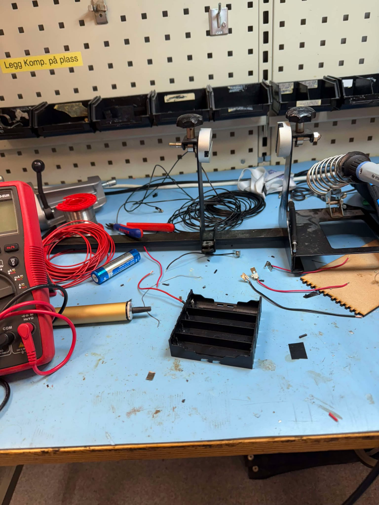
The battery pack is placed in a battery holder specifically made for 18650 lithium cells, however when I got it finally, I had to completely start over again and almost rip apart the whole battery holder along with the cables. The cables were changed with thicker ones which have a max current rating at 9A, additionally they are in copper, unlike the ones which were in some sort of aluminium coat wiring.
Copper is a much better conductor than aluminium, in fact you can compensate for thinner wires if you have copper inside of them, and it dissipates heat easier, so absolutely a win for us all.
The purpose of a BMS is to protect each cell in the battery pack from charging above a safe voltage, in the case of 18650 Lithium batteries that is around 4.2V, besides – higher voltages increase the internal pressure in the cell, and leakage may occur. It simply is not something we can take a risk on, when dealing with a battery pack without a BMS.
The BMS I used is a HX-4S-F30A, which is specifically made for 3.7V lithium battery protection.
Aside from that, the BMS also monitors current and temperature of the battery pack, with that it ensures safe operation and extends the battery’s lifespan – finally, it also balances the charge between cells, ensuring that every cell maintains similar voltage level.
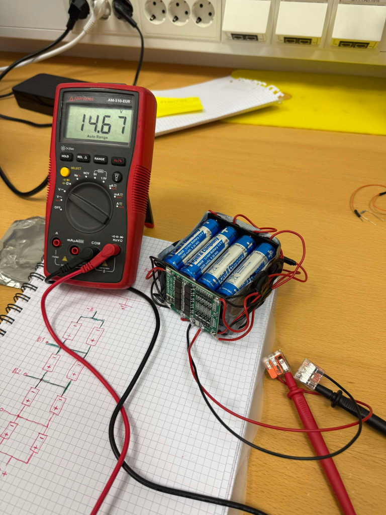
The circuit now has actually more power than needed, we’ve decided to go over the 12V and up to the 14.8V voltage supply range, however that was convenient for us as everything can operate within that range, including the servos. Reason for that is simply that we couldn’t find a configuration where we could get to 12V with the same cells, and in this case it is better to go above the recommended voltage to ensure an efficient operation.
Ruben Henriksen
I redesigned the storage container using sheet metal to make the plates for the storage container that I then laser cut in some plexi glass that I then heated and bent into shape. In this design I also added some slots that with laser cut plates could be placed to make separate rooms to sort the different objects into. The decision to make the storage container this way was mostly for aesthetic reasons but it also fulfills our requirements.
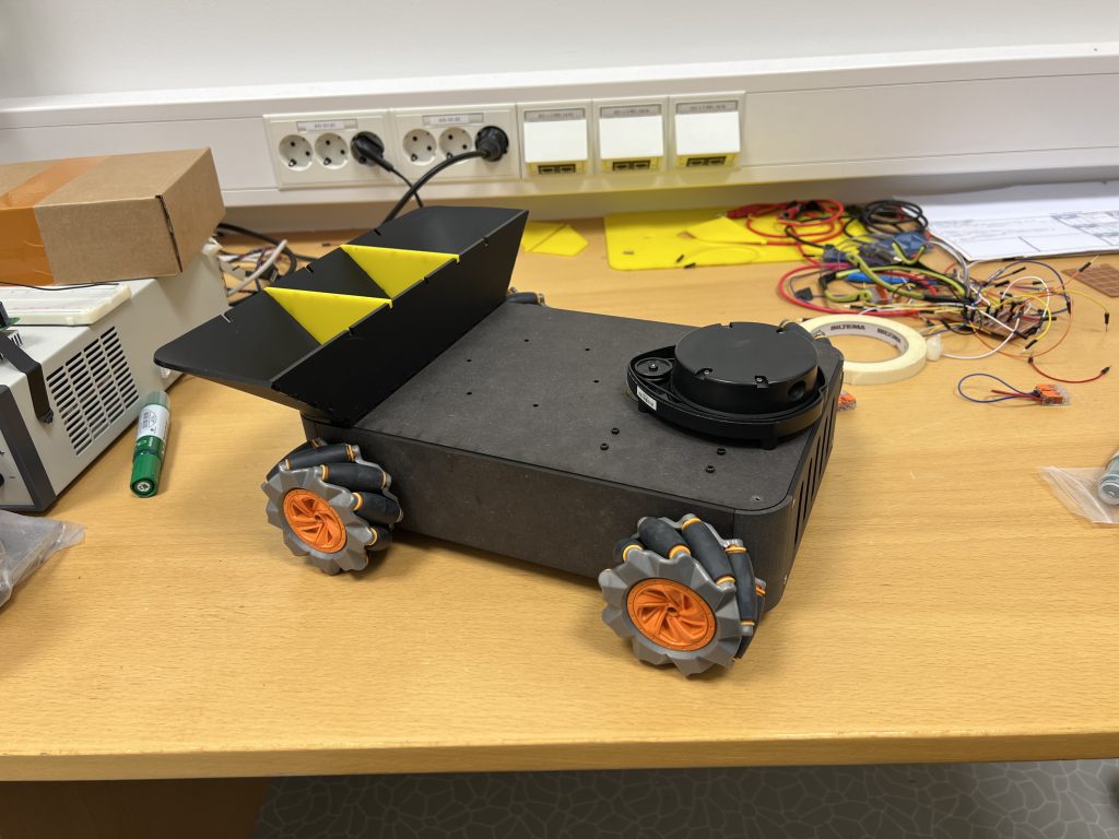
To make the storage container I heated the bends with a heat gun and carefully bent them by hand until they fit into the slots of the forward panel. I then added some caulk in the gap.
I also moved the Lidar and arm so they now fit without interference.
Next Week:
I heard that the electronics engineers have received some stand-offs for their circuit boards, and finally made the battery. So I will fix the placement for the internal components, Make a camera adapter and a box for the batteries.
Philip Dahl 🔋
I was looking into ideas on how to get a more compact and clean circuitry inside the base of the robot. It was through this I discovered that the solderless breadboards used up until this point, has a current limit. They cannot handle much more than 1A before showing signs of damage. Since more than that would be flowing through the circuit, it was time for a replacement.
I had a prototype board laying around, so I began with that. I soldered one of the drivers on it, but saw that I should have inspected the board beforehand. It was very difficult to make tracks, connecting pins to the necessary wires. This did not seem like a viable solution, so I decided to switch to another board. Removing the driver was not as easy as soldering it on, so I spent more time than I like to admit, retrieving it.
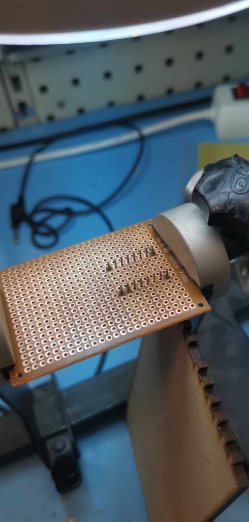
The other board I used made making tracks a bit easier, but it gave me a challenge due to its quality. As this was likely a cheap breadboard, the copper “stickers” where the solder would stick to, simply came off in some areas if heat was applied for too long. It set me back a couple of steps but I had no plan to give it up, continuing next week.
Kevin Paulsen
This week has been a bit bittersweet. We received the new powder-printed Nylon parts that Ruben arranged for us, which was exciting! But due to my lack of experience with powder-printed Nylon, some of the tolerances were a bit off from what I expected. For example, the “chambers” where the servos are supposed to fit securely ended up with a bit more slack than planned.
Since Nylon powder printing is limited and Ruben is the one with access, and with the project deadline quickly approaching, I had to get creative. For some parts, I managed to make it work by shoving folded paper between the servos and the chamber walls to reduce the slack. However, on the gripper assembly, the fit was too loose, so I had to revert to PLA-printed parts for stability. Even though the all-Nylon arm looked impressive, a cool robot arm isn’t much use if it doesn’t work as needed.
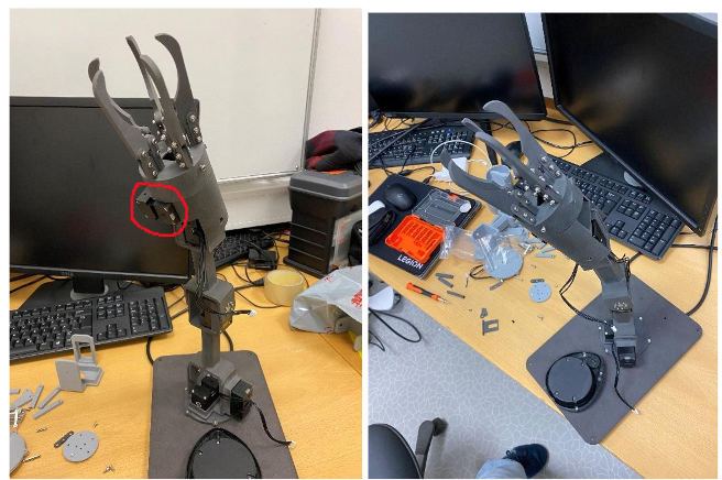
Here you can see the all-Nylon arm. The servo marked with red kept on falling out, so this is one of the places I must use the previously made PLA part.
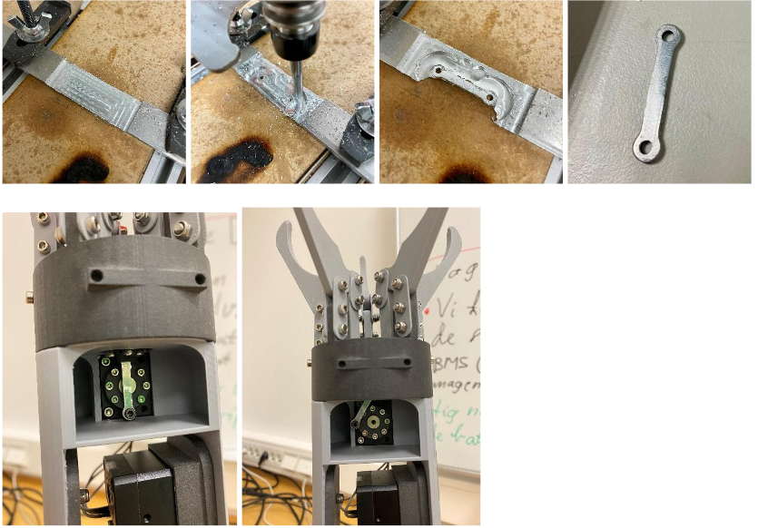
I also made a few changes to the gripper sticks that control the gripper claws, adjusting sizes and tolerances to make the grip tighter and sturdier for picking up the ball. As you can see in the pictures, the previous fit was a bit too loose, allowing the ball to slip out. The updated fit is much tighter, giving the gripper a more secure hold.
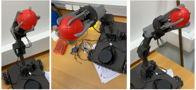
A big thanks to Rasmus, who used the CNC machine to make the servo-to-linear stick in aluminum. This piece is critical for the gripper’s function, and being both the smallest and weakest part, the aluminum upgrade should give it the durability it needs.
