Sergi:
During this week we tested the robot with the simulation code in order to make it move and we figured out that the motor on the upper base wasn’t able to move all the robotic arm by itself. It was moving but only when we were increasing the voltage more than 5V and these motors are not made to resist more than that. So we arrived to the conclusion that we had to redesign the upper base and the first arm. So I took care of all that and I redesigned myself both parts and send it to Richard to 3D print them. As the motor wasn’t powerful enough we thought of instead only one servomotor lifts all the arm, put two of them in the upper base. That is going to make much easier lift the whole arm because they will divide the force and is going to be more stable the whole lifting. Then the arm is going to be in the middle of the two motors, so we had to redesign it as well. Here are the photos of the final result, the redesign consisted of several things:
Upper base: I made like a ring on the bottom of the piece to increase the stability and subjection of the upper base.
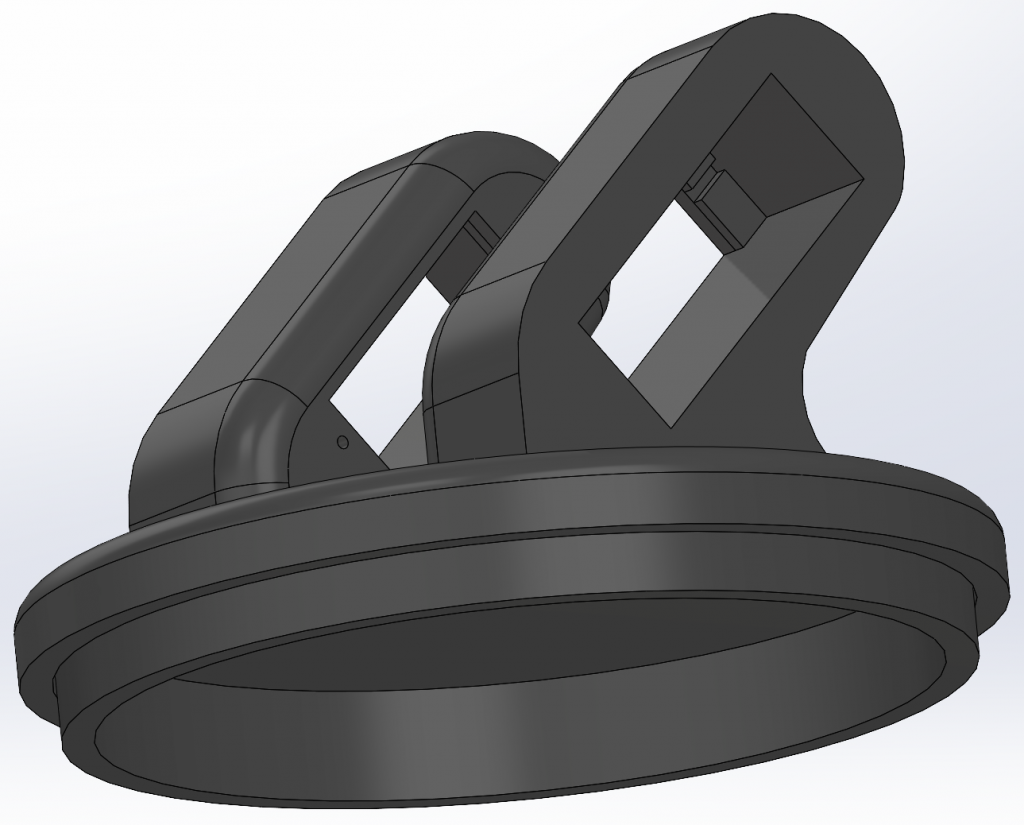
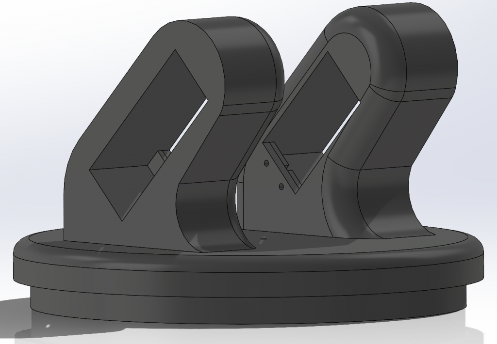
Also I reduced the thickness of the part where the screws were going, to make it easier to screw it and with that we don’t need that much long screws. However I made a bigger hole for the servomotor to be able to fit the whole servomotor inside the hole and be easier to screw it. Finally I did the mirror of the piece that holds the servomotor to be able to have the two of them at the same position.
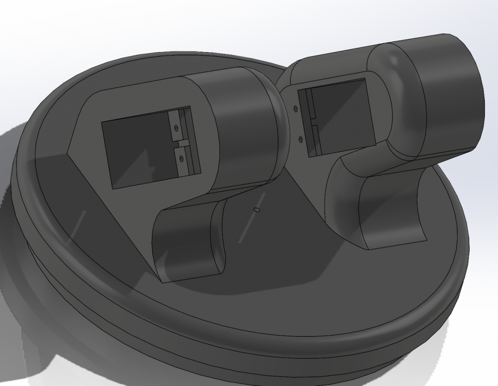
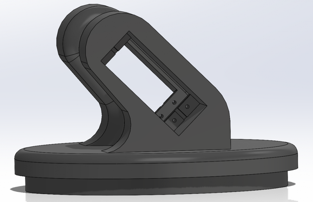
Arm: For the arm I modified one end, the one that goes in the middle of the two servomotors. First of all, I filled the part that was empty and then I made the same sketch but on the other side. Then I extruded the cut until 8mm for making it easier to screw it. Finally I mirror it to the other side creating before a plane to make the symmetry. This way at each side of the arm it can be connected a servomotor and will make it work.
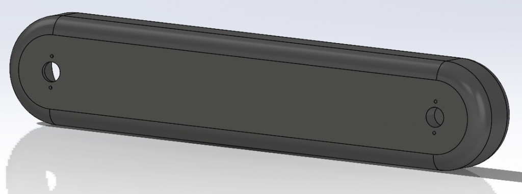
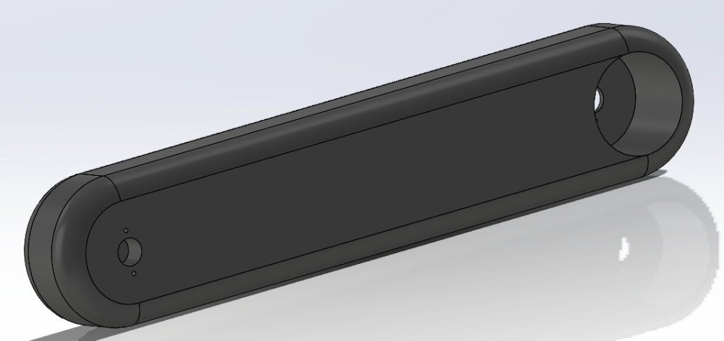
At the end of the week, I also started with the help of Pamela the assembly of the robot with the final redesigned pieces:
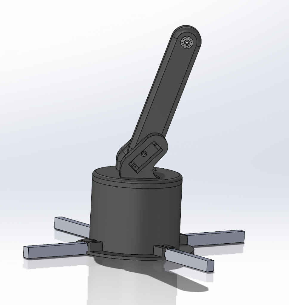
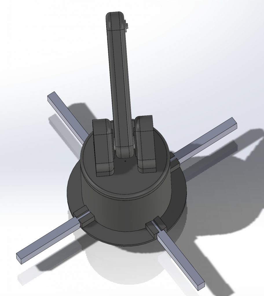
When we finished the whole assembly of the robot, with the help of Pamela I did the FEM analysis with the new pieces. I put a force of 0,2 N because we are lifting 12 grams plastic bottles (medium size) and I also fixed the whole base. With all these conditions, here are some photos of the result that we got:
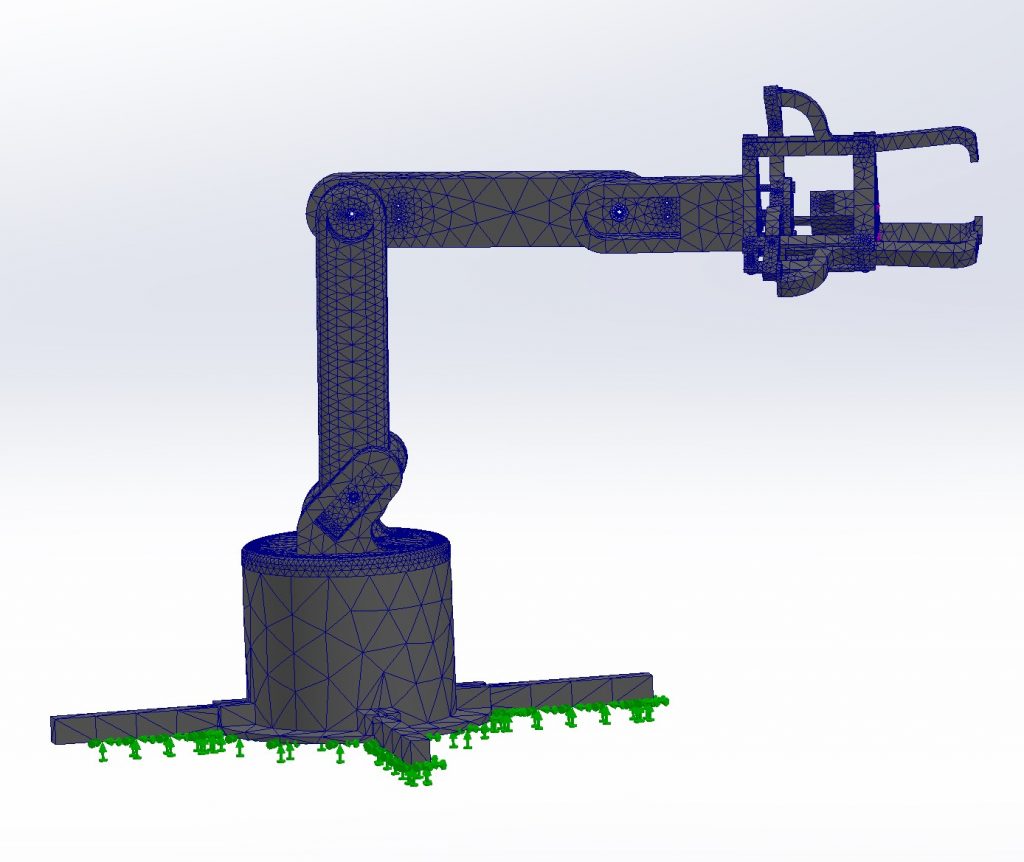
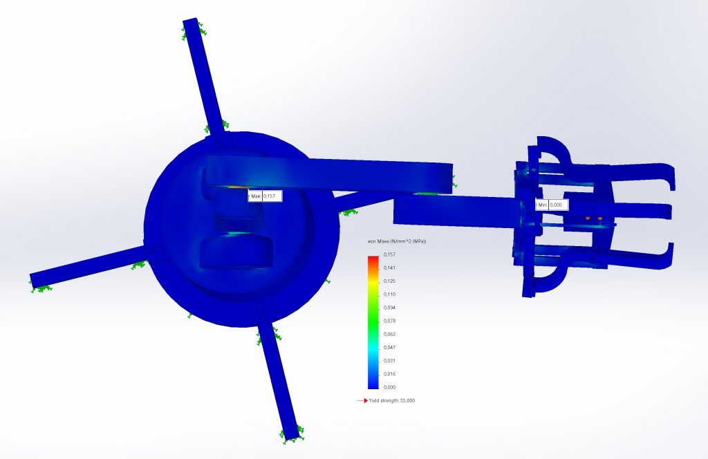
We can conclude that the weakest point is the joint between the first and second arm, so its the most critical zone where its easier to break. On the contrary, the safest point is in the gripper, so its the least likely to break. As it was practically our first time with FEM analysis we watched some youtube videos to learn how to do it and understand the functionallity and requirements. This was the video that I followed:
https://www.youtube.com/watch?v=nAhd4_bveTA&ab_channel=3DProductDesigning%26FEA
Pamela : This week Sergi and I have finished the final assembly with all the final parts. To do this I have modified some parts to be able to do the FEM analysis better. On the other hand I have changed the origins of the parts because the students in charge of the code needed to have them aligned when simulating.
Here is the final assembly in order to do the FEM analystist and after are the parts that I changed only for the joins because I skip the motors.


At the end of the week Sergi and I did the FEM analysis. In it we can see that the parts where the most pressure accumulates are at the points of union between the arms.
Jacob:
This week me and Sergi went over the parts of the model that did not work properly, namely the base. The previous base with one motor could not sustain the whole arm. So we remade it to be able to fit two motors instead of one. We also added a ring underneath for better support of the “upper” base to better stay on top of the rest of the base bellow.
This way we also redesigned the arm part connected to the base to be able to support both motors.
When I was assembling it however, it turned out we reduced the thickness of embedding for the motors on the base a bit too much and I needed to add some material and make it centered. Luckily I was able to do so and screwed the motors in place.
Me and Adam also redesigned the claw a bit, namely the lenghts of the joining flatheads between the triangular bases, and printed an embedding for the servomotor for the claw. This was an easy fix and an easy assembly.
The arm was ready for further testing.
Adrian:
Since the testing has been inconclusive at best, I decided to reach out to our professor for aid. It turns out that the external power supply we were given were faulty, as well as a couple more servo motors. By this point we have changed and swapped almost every component which isn’t the 3D printed arm itself. But thankfully, it helped since the results of testing afterwards are quite hopeful. By the end of the week, the arm is given to Farah, and I turn my attention to the depth camera.
Adam:
Redesigning the claw and helping with assembly. (Jacob’s post)