Kristian – Week 10
This week we figured out how to solve the connection problem regarding the magnet sensors. The sensors need 3 inputs. Ground, Vcc and signal. We figured we wanted to use female to female wires from the sensors to the Arduino, because the Arduino shield has male output vs the normal female output. The wires were a little short for our liking which resulted in getting a handful of males to female wires to have the option to make it longer, if we want it or need it.
When thinking about the magnet sensors and the ability to advance the human move (after it is done) to the machine would heavily rely on the sensors doing its job perfectly. My idea here was to use the Arduino kit 8×8 led matrix to show the player what the sensors acknowledged and what they are ready to send to stockfish. This will tell the player that his/her move is the same move that will be sent to stockfish.
I started off scouting the web to find some information on how to wire the 8×8 led matrix. This is the 1088BS led matrix. I found one from Arduino which looked completely similar but had a completely different wiring

This was my first trial and error and used up a lot of time trying to solve this both with coding and wiring.
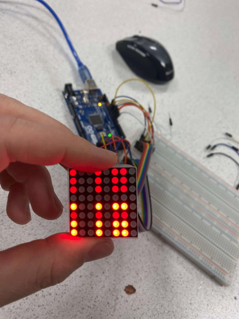
At first just a couple of LEDs were on, and it ended up looking something like this
Some lights were brighter than other, because the resistors were placed on the wrong to the matrix

eventually I found a new way to implement the wiring to the 8×8 led matrix


Now I tried once more and I managed to get all the LEDs to shine, but like earlier some were bright, and some were dull.
After some more testing in Arduino, I managed to get all LEDs to shine bright.

After managing to turn all LEDs on I decided to create a function that can light up a specific one.

I then made a function for switching between 2 lights showing the move that has been detected. This is not yet implemented in the main Brach, but hopefully during the following week.
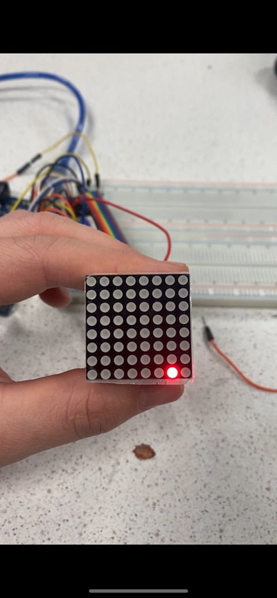
Here you can see a video of the led matrix showing a knight that has moved from g1 to h2:
Arduino code:

Ulrik – Week 10
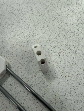
With the robot mounted together I started the process of designing and producing the crane frame. This is a crane hook block that will travel up and down on two guide rods to counter the pendulum-effect that comes into play when the gantry moves. The block contains two guide holes and a hole to mount the electromagnet that will pick up and drop the chess pieces.
Also added the pins that will connect the crane to the bottom rails. These keep the crane steady, but they are wobblier than expected. I suspect them to be steadier when the weight of the motors come on top of the bottom plates, but this can prove to be a future problem to be solved.
I have redesigned the foundation for the upper motors, so that it can fit the new frame system. The next part will be to cut it in the laser cutter and replace it with the old one. Then what remains is to attach the motors and electronics together with routing the wires.


Sondre – Week 10
This week I’ve finished the rack and cog in 3D and laser cut it so it’s ready to be tested on the model. Also started to design chess pieces.
Jon-Eirik – Week 10
This week we found out that a mux was not possible anymore, but Steven had fixed an Arduino MEGA sensor shield.
This shield can take 68 inputs, so that we can use it to have control over every 64 positions on the board. Having this means that we need another Arduino to control the motors, since we need more than 4 inputs for those.
We also got hold of a bunch of females to female and female to male wiring, so that we can connect every sensor to the shield. We are planning to solder everything else but the output.
Emil – Week 10
I’ve not done much this week since I’ve been busy with other school related work. I started the week by getting together with Kristian and Jon-Eirik and we started planning on how we were to place all the sensors under the board. If we needed to weld it in place and how we would wire it up.