Ulrik – Week 9
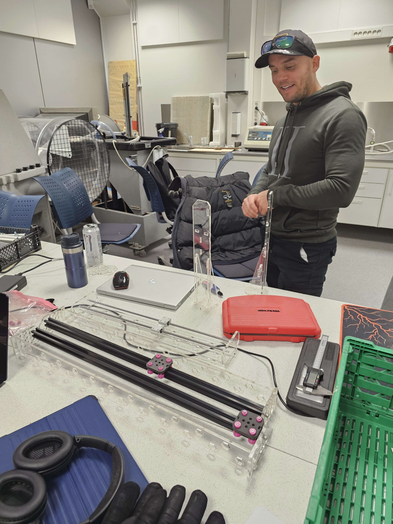
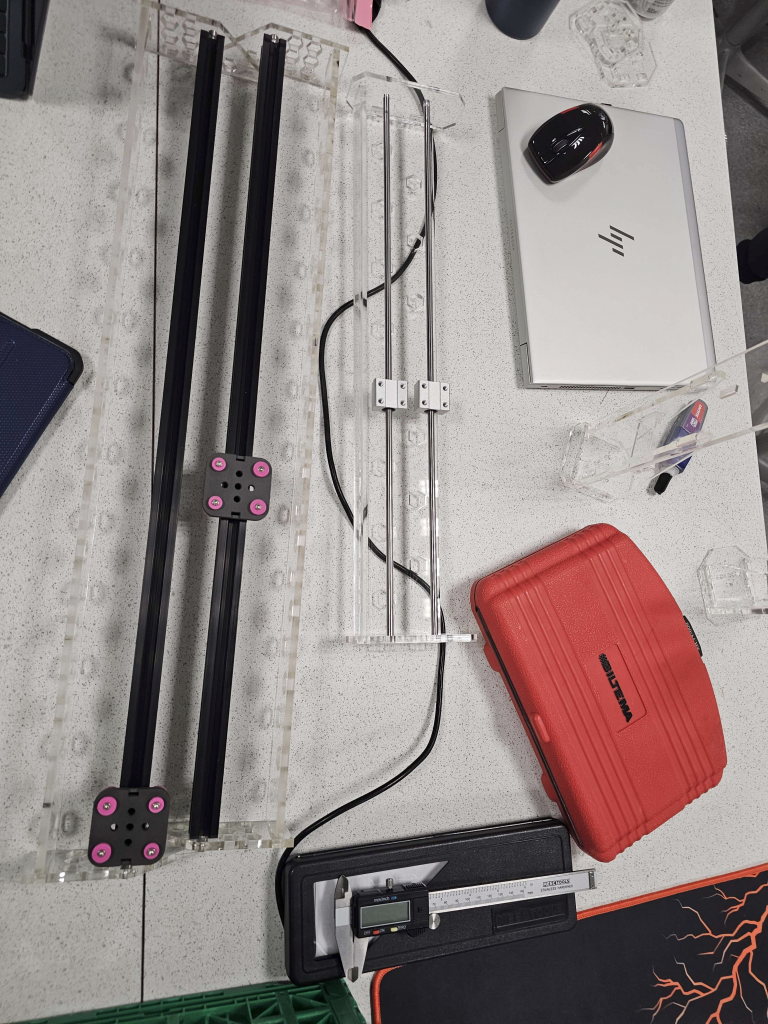
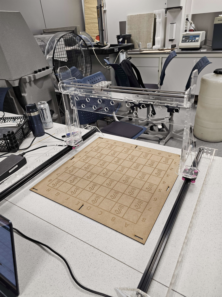
On Monday we mounted the robot together with bracings and superglue. The bracings were cut and the pieces from the old design had to be post-cut in the laser to allow the new parts to fit.
The robot was wobbly and unstable before and this worried me. I spent a lot of time thinking of different solutions. From wires diagonal profiles, but finally landed on the bracing system. Turns out, not only was it easily adaptable to the prior design, but the gantry is now rock-solid! Couldn’t be happier with the result.
I have printed some of the fittings to connect the gantry to the V-profile carries, these are the white “fittings” on the pictures. Plan for next week is to fit them together along with the motors. Awaiting a more refined rack-and-pinion system from my mechanical engineering-colleague. I hope, with the motors fitted, the pre-programming from the data crew, it will be plug and play!
Sondre – Week 9
This week I’ve finished the rack and pinion in SW. I have also generated some 2D drawings and dxf files and laser cut some parts for the gantry.
Emil – Week 9
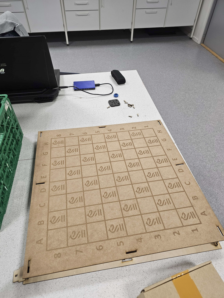
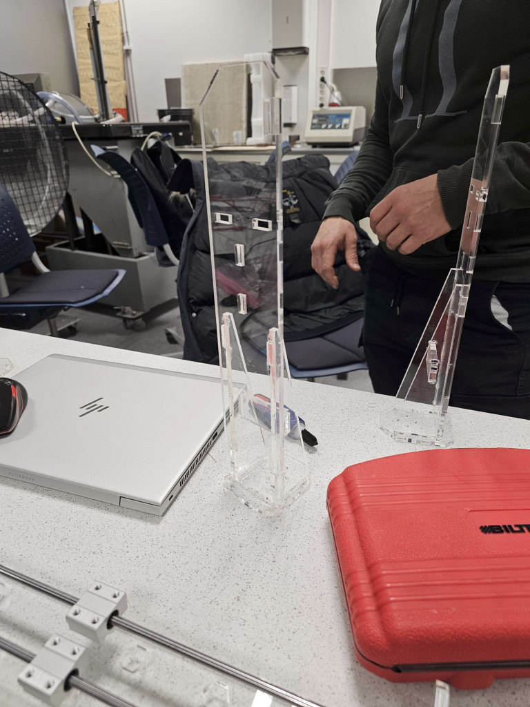
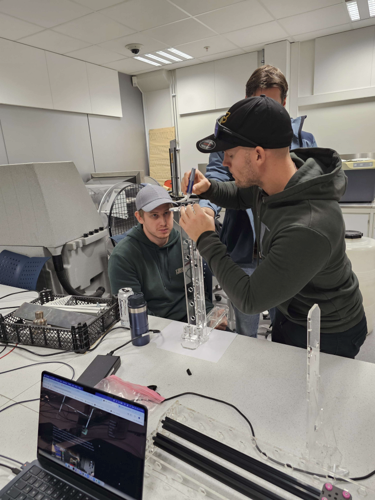
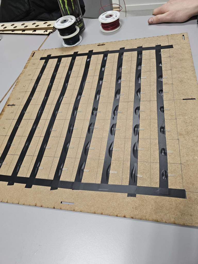
This week we sat down together to figure out what and how we are going to things forward. We talked about using multiplexers and we planned how to connect all the sensors with wires. We also started to put together our machine. As u can see higher up in the post, we put all the pieces we made together and glued them so they would stick. And it worked out great.
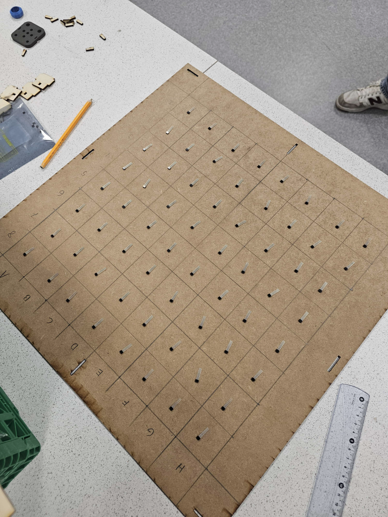
Other than that, we have now gotten our magnets and sensors so we can now start to connect all this and wire it up.
Here are some pictures of us building the machine:
Jon-Eirik – Week 9
This week we started to get all the parts put together; we have started to think about how we would wire all the sensors. If the best idea is to just pull wires for ground and connect every sensor to that and wires for 5VCC and connect every sensor there as well.
For the signals every sensor will need its own wire, so the signal won’t be disturbed by another.
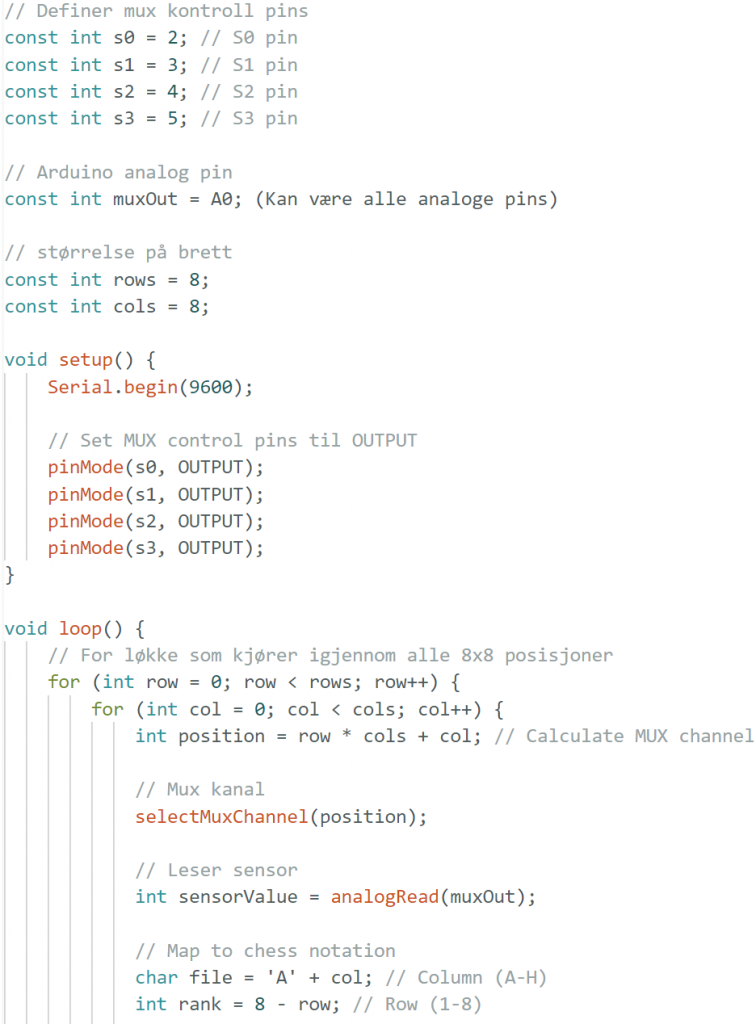
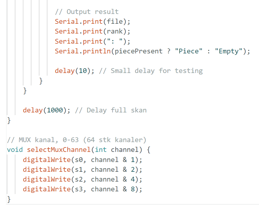
I’ve also started to work on some code that will work with the MUX, we have yet to receive the MUX, so we have not been able to test the code with 1 or more sensors. We have gotten to test some of the sensors that are connected to the board, and they give out the signal we need to implement.
We want our code to end up with reading where a piece has been moved from and where it got moved to. This is so we can get it as a chess notation we can send to the AI we are using, so it knows what moves has been made in chess terms.
This code is made with the thought of us getting a 16input MUX, but its changeable if our mux can handle inputs.
Kristian – Week 9
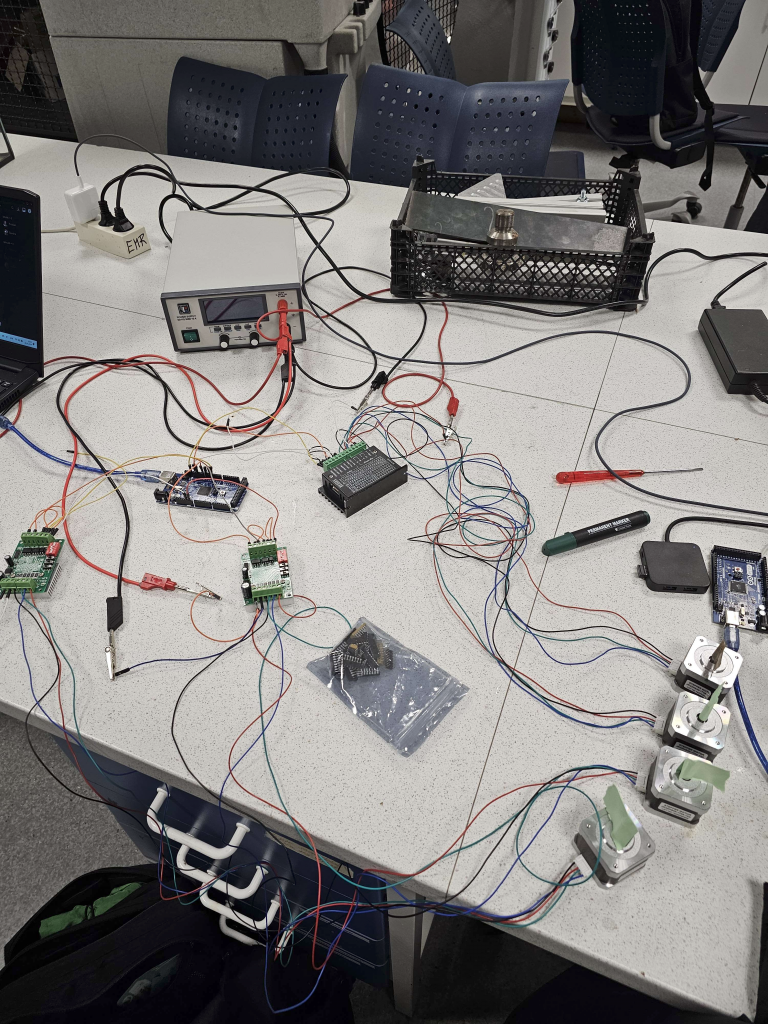
On Monday I connected all the stepper motors and drivers to test the code I had implemented last week. From what I could tell it seemed to work as intended. When the stepper motors are assembled to the gantry, I can finally see for sure that it works as intended. This remains to be seen 🙂
A lot of the parts from the gantry were finished and ready to be put together this week, I helped a bit with the assembly. On Monday we received our sensors and a box of cabling for ground and the “live” cable.
On Monday I also used some time to understand how a mux works and how we can use it to read the humans’ move.