21.10.2024 – 27.10.2024
“The future is not something we enter. The future is something we create.”
-Leonard I. Sweet
Group Summary
Dearly beloved,
we are getting ever closer to completion of a fully functional project. Us computer people have spent most of our time optimizing code. The mechanical engineers are still going strong with their phenomenal simulations and drawings, and the electrical engineer Vetle is doing, I don’t know, electrical stuff, dark magic maybe? Isn’t that what all electrical engineers do anyway?
Individual Summaries
Eirik (Data):
So, we tried running the optimized code on Monday, and quickly found out that threading alone was not enough to get the fps up to a reasonable level. We then tried to use a Raspberry Pi 5 to run the code, instead of a Pi 4 like initially planned. There were some improvements in the framerate, so I decided to try and optimize to code even more. After searching around on the internet for a while, we learned that reducing the video resolution, the size of the video stream and image format could improve the fps a lot.

Here we can see all the modifications to the class “VideoStream” that will help the code to run smoothly. With all these modifications the code began to run at a relatively appreciable frame rate, but I wanted more! I once again went back to the internet to find other ways to improve it, and the last modification I ended up doing was frame-skipping.

Leaving out a frame once in a while ended up improving a lot. We decided that the frame rate we ended up on was doable, so we will not do anything else to improve this code for now.
After finishing the code for our camera, I started looking at the code and connections for our moving target. The target will consist of an IR-sensor that will detect when a hit has taken place. The target will be fitted with LED’s that will light up green when you can shoot, and directly after a hit the lights will turn red while the target moves. The code for this can easily be implemented in Arduino:

As of now, the most important part of code that needs to be fixed is the aiming procedure for the system to shoot back. This will also probably be the most difficult part of the entire code to run properly. The whole principle is that the computer vision code will detect the player in frame, then it must somehow convert that image to coordinate of some sorts so that a servo motor can be used to rotate, following the player as they move around in the room.
Robin (Data):
To start with, I joined in on helping with the framerate of our computer vision module as Eirik wrote about. Then I had to figure out what kind of functionality we needed for our project so it is ready as soon as the PCB is in our hands, some of which where:
- Movement system
- Turn off/on target sensor (for when the player can score points)
- Change color on LEDs
- Point system shall be shown on a screen
- Implement GUI
- Weapon control module
So I started to work towards implementing the Movement system in Arduino code. So I had to learn how to control a stepper motor and got that working, but then I wanted to be able to control the Arduino through python. And found the COM port and were able to send information to the Arduino.

One thing led to another, so I to make a simple GUI where I could control the stepper motor and ended up with trying to learn QT and the pyside6.Qt modules. In the end I ended up with something that could connect and send information to the Arduino through the GUI. Some of the code below and video below that.

Fredrik (Data):
I went back to the code of last week and managed to do it with threads. I did the same as last week but apparently this time it works. So now the point system will be easier to control when it’s active or not, letting us have more freedom with the system.


After that I started to work on making the GUIs that we need. So i started by following this YouTube course hoping to get the knowledge i need to make the desired GUI. But it didn’t touch on video streaming, but that is only a few google searches away, i bet.
Vetle (Electrical):
I switched the 5V voltage regulator from a MAX20008 to a LM61480Q5 from Texas Instruments since the datasheet from Analog Devices was all over the place when it came to the equations for selecting the component values. It was an easy switch because of the easy-to-read documentation from TI.

To connect the 24V power supply to the PCB I have chosen a connector from Phoenix Contact with the manufacturer part number 1017503. This connector is rated for 32A, but the power supply is only 24V 15A (360W). The connector to connect the IO is a 16 pin connector from Phoenix Contact. It has two connectors for the stepper motors and two for the servo motors. It also has additional pins for 5V so it can power parts that need 5V if it is needed.

Kadir (Mechanical):
Worked on shoot-back.
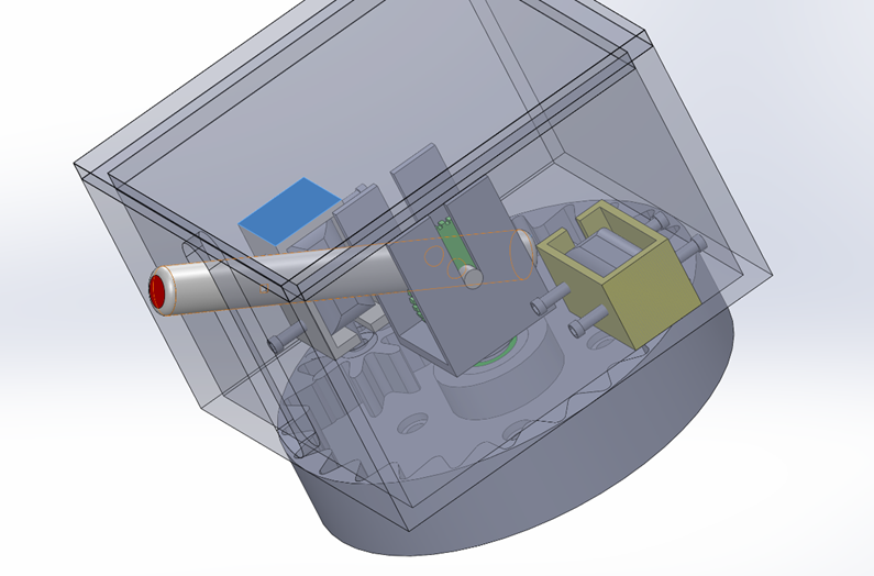
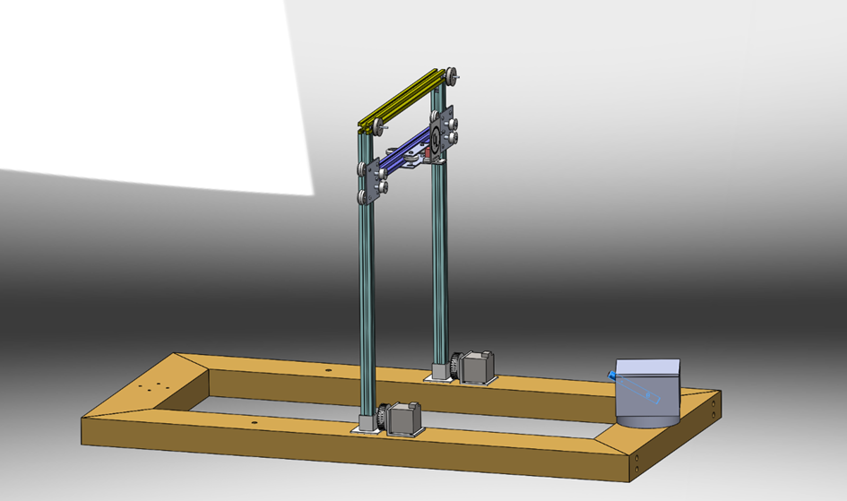
This week me and Hans , we were working several updates and improvements were made to the laser gun design and motor support system. New bases with better gears were created to allow smoother and more flexible rotation . The ground base of the laser gun was also redesigned, with new measurements that meet the needed performance standards. The columns responsible for moving the gun up and down were carefully adjusted, with improved simulations for greater accuracy.
A new box was designed to hold the motor for rotating the gun , along with a separate box for the motor controlling horizontal rotation. This setup improves efficiency and helps prevent malfunctions.
With Hans’ help finishing touches were added to the prototype to ensure it is easy to manufacture and performs well.


Hans (Mechanical):
The model was redesigned to accommodate a dual-belt system, which improved load distribution, stability, and control. This configuration allows for smoother and more reliable movement while reducing wear. The bearings were replaced with higher-quality options to support the dual-belt system, resulting in reduced friction and noise, while enhancing efficiency and durability.
Assistance was provided to (Vetle )with test runs and the calibration of end stops, ensuring safe and precise limits for system movement to prevent overextension. During testing, it was revealed that the belts tended to slacken over time, so additional stops were implemented to maintain tension and stability, thereby enhancing accuracy and
extending the system’s lifespan. Support was also given to Kadir in designing the laser gun and determining the appropriate measurements. Additionally, modifications were made to the gears, and bases were designed to support the small motors.

