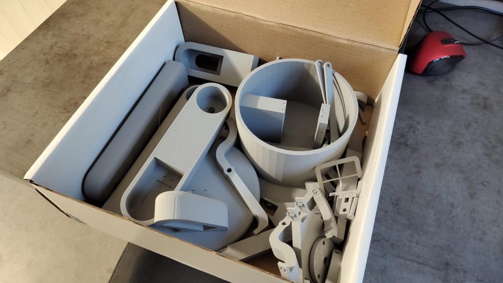
The nineth week we got the 3D model printed from Richard.
Individual work:
Adam:
Now we have received all the 3D printed parts, we got to the assembly, but in a few moments we realized that we have made a major mistake by not accounting for tolerances of the 3D printer. So now, we have a lot of parts good for nothing and little time to spare. Sadly there was nothing to do about it in to the point was already almost end of this week.
Adrian:
With Farah’s revised URDF file, I took over the work of programming basic movements to test the integrity of the arm under its own weight. It is also to test the strength and speed of the servos. If they are slow, we’ll take it into consideration when automating the movements.
Jacob:
We have finally received the 3D printed parts and started to assemble, but we quickly found out that we can’t continue. Due to our inexperience in assemblies and with 3D printing, we have made a lot of tolerance errors and the parts would not fit. We have tried a lot of things to get it assembled but alas nothing worked or would take an awful lot of time. So we have started to redesing the model with tolerances in mind this time.
Farah:
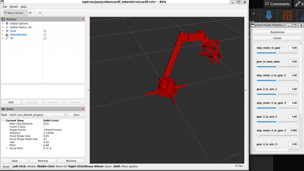
After receiving the robot model from the mechanical team, I began creating a detailed URDF file for the robotic arm. This involved specifying each link, joint, and connector. From the base components to the grippers, completing the URDF setup took considerable time. I went through several revisions to address errors related to joint relationships, parent-child linkages, and correct spatial configurations in RViz.
One challenge I encountered with RViz configuration was that, despite having the correct origin settings, the robot sometimes appeared assembled far from the intended origin. This required further inspection and adjustments in the URDF to ensure that all components began at the correct origin point. Additionally, I faced specific issues with joint relationships, particularly between the stepper motors and gears, which affected the assembly and rotation simulation of the robot model.
To resolve these issues, I rendered the model in Blender, adjusting the origins and rotations as needed, and then re-uploaded the model to ROS2.

For the kinematics part I delegate to Adrian to work it out while I move on researching a way to integrate Intel RealSense Camera for object recognition
Pamela:
During this week we were able to get our first 3D print of the first design, however some pieces did not fit because we forgot the tolerances. So Sergi and I decided to modify them and sent them back to Richard to print them again. I was in charge of the base part, which in principle was fine in terms of tolerances.

Sergi:
During this week we got our robot 3D printed, but as was our first time for all the mechanical engineers dealing with the 3D printing method we did not take into acount the tolerances of the printing and a lot of pieces didn’t fit each other.
So during this week we modified all the tolerances and make the holes a little bit bigger to make all the parts fit each other and be able to assembly all the robot. Once I finished modifing the tolerances we send it to Richard to print it again. I was in charge to change the tolerances of the legs to fit with the base itself, the ones responsible to fit the servomotor correctly inside the base and the cylinder that comes off the last arm (3rd) to be able to connect it right with the robotic hand (gripper).
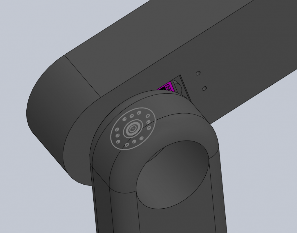
I also did some holes to be able to stick the servomotor with the robotic arm with screws:

