Github
https://mavbs@dev.azure.com/mavbs/MicroMouse%202023/_git/MicroMouse%202023
Andreas
Week 12
This week has been spent trying to ensure we have a finished product within the delivery date. This entailed fixing and decluttering sensors that were half-hazardously soldered together a month and a half ago, soldering the rotary encoder circuitry, and preparing to model the motors.
Since we wanted to switch the motors and add rotary encoders to the robot, we decided that we would have to change up our entire design. This meant we had to disassemble the whole robot and transplant it into the new, 3D-printed chassis. During this process of disassembly, we realised that some of the sensors had been broken and there was a lot of clutter in the wiring. This led to me spending the week attempting to save the components and soldering new sensors so that we could assemble them in the new chassis.
Before this, though, I performed tests so that in a perfect world, I would be able to model the new motors in MATLAB and hopefully be able to simulate the intended motor controller, though this was set on the back burner when I realised a lot of work would have to be put into the circuitry of the robot. The tests were intended to find the inductance and resistance of the motor by varying its frequency. This would enable me to use the general motor transfer function so that I could simulate a rough equivalent of the motor and create a controller, sadly we will most likely not have the time available to do this.
Since the next week is the last one, I will mostly be spending it fixing the previous bits to assemble the bot and assist the computer engineers as much as I can so that we can hopefully be able to finish a labyrinth in however much time it takes
Week 13
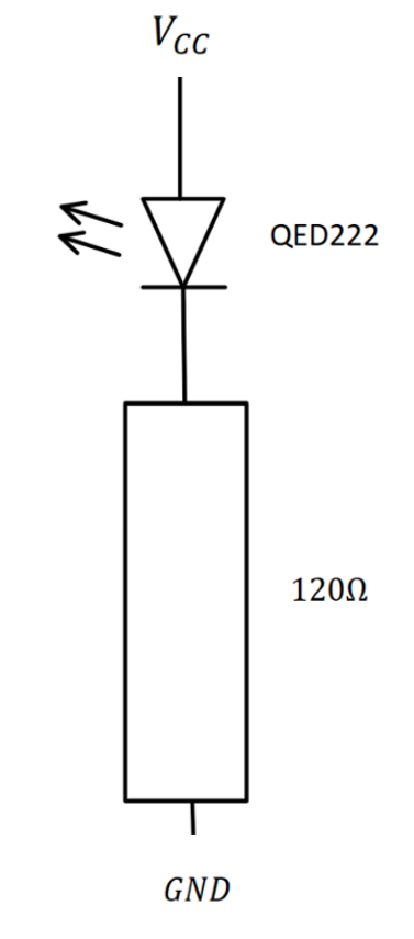
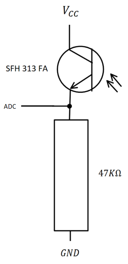
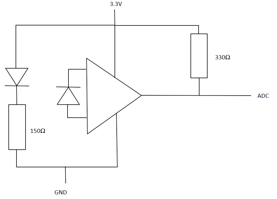
As predicted in last week I have spent the week fixing the electrical circuits and doing some final documentation on some of the circuits we have slightly changed. Luckily, since we decided to do the filter digitally instead of analogue, we simplified the circuits to such a degree that simulating the circuits was overkill.
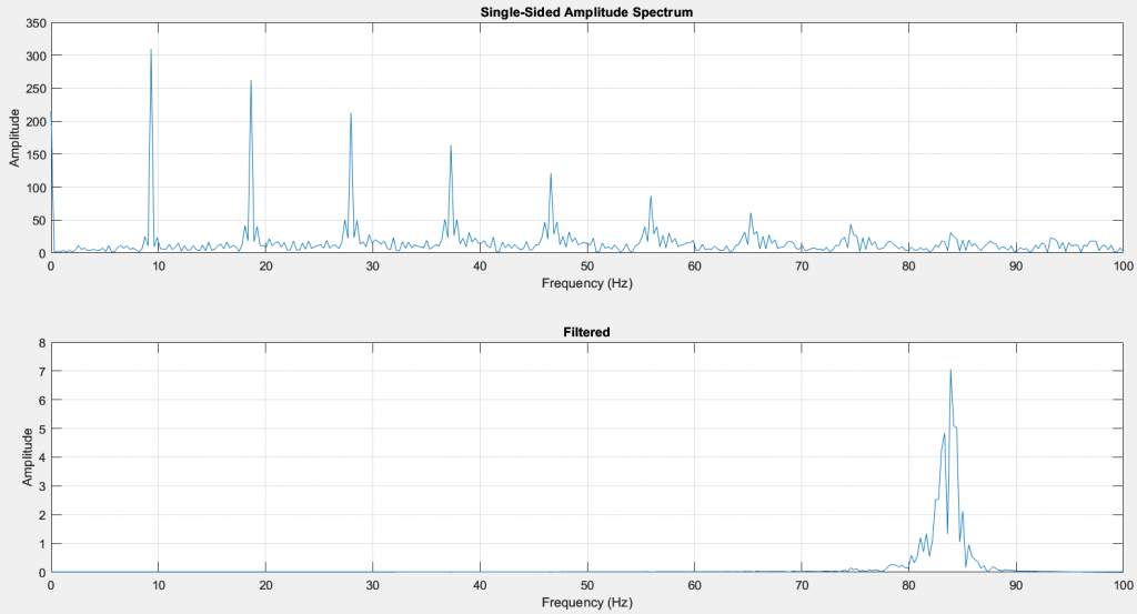
On the programming side, I have been improving the filtering and ensuring that my MATLAB code is readable. I have also assisted Bendik in making a PID controller to the best of my ability, though we moved away from it as we had little to no time actually figuring it out.
I also assisted in the logic behind the centring function of the robot, ensuring that the robot stays in the middle of the track when driving in a straight line. This worked basically by checking the side sensors to see if there was a significant difference, then turning to a specific angle towards the middle, driving for a calculated distance and straightening it to run parallel to the wall again. This function is mostly theoretical as of writing this.
Practically, I have mostly been fixing broken circuits and ensuring that they all fit within the robot and function as intended. One of the motors was broken in shipping from Marte’s home to the school and needed replacing, as well as one of the sensors giving off some weird sensor data. I will be spending some further time attempting to fix this.
Bendik
Week 12
This week, while I have been waiting for the hardware to be ready, I have created a main project in ADA to include all the different pieces of software for the Micromouse. This includes a PiD controller and the IR signal filtering algorithm. When Vendel finished implementing her path finding algorithm I will also implement that into the project. The idea is to use tasks to make a concurrent program. I also helped out with soldering the wires for the new motors on the MicroMouse.
Week 13
This week I tested my PID controller and implemented the wheel encoders into code. I wasn’t able to get the PID controller to work, sadly. As time was of the essence, I decided to comment out the PID controller, and implement my own speed controller to try to get the mouse to drive straight.
Using the wheel encoders, I made code that adjusted the motor speeds via PWM (pulse width modulation). For every pulse of the encoder, I added to the “Distance Travelled” variables for both the wheels. If one of the wheel travelled further than the other in a certain amount of time, then the motor speeds were adjusted to compensate. This worked decently well but still needs calibration.
I also made a “centering” procedure, that takes in the direction and distance that needs to be driven towards the center, given that the mouse turns with a 31.5 degree angle towards the center. This has yet to be tested properly. I also mase a procedure to turning the mouse 90 degrees that also needs to be tested. When the front IR sensor senses that a wall is nearing, it will turn 90 degrees.
The last minutes before the deadline will be used to test the mouse in the maze and make a short video, brushing up the code in the process. The week towards to presentation will also be used on coding to integrate everything together, the algorithm, wheel encoders, IR sensors and hopefully get it working properly.
Marte
Week 12 & 13
De siste par ukene har vært hektiske for å bli ferdig med mikromusa. Disse to ukene har jeg laga to design, produsert deler og ordnet sammenstillinger. Jeg har hatt mye kvalitetstid med 3D printeren jeg fikk for et par uker siden, og i begynnelsen brukte jeg mye tid på å få deler til å passe sammen mtp toleranser og krymping, men det har gått litt bedre etter hvert som jeg har fått mer erfaring og kjenner printeren bedre.
Planen var å teste med forskjellige materialer, men vanskelighetsnivået til PLA har vært høyt nok for meg nå i starten.
Det var dessverre først nå i uke 13 at jeg fikk hardware helt ferdig på den nye varianten, så data og elektro har dessverre blitt hindra fra å kunne gjøre noen av oppgavene sine og testing pga dette.
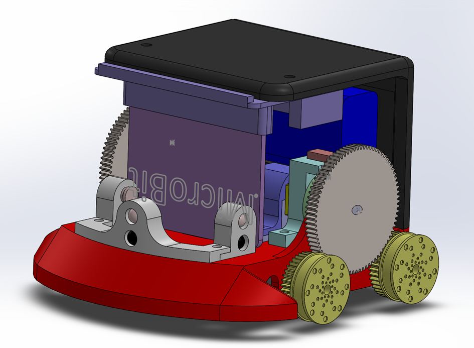
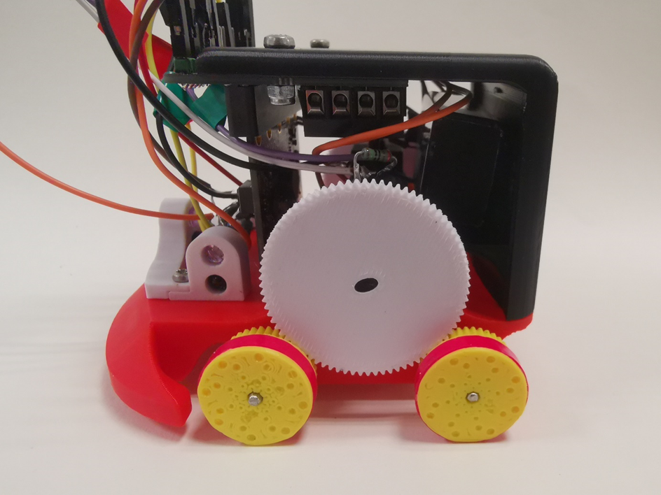
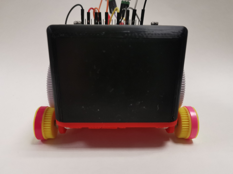
Jeg lagde først et design med de nye motorene, SolidWorks fila har dessverre kræsja på denne første varianten, men her er bilde av ferdig produkt av det første designet:
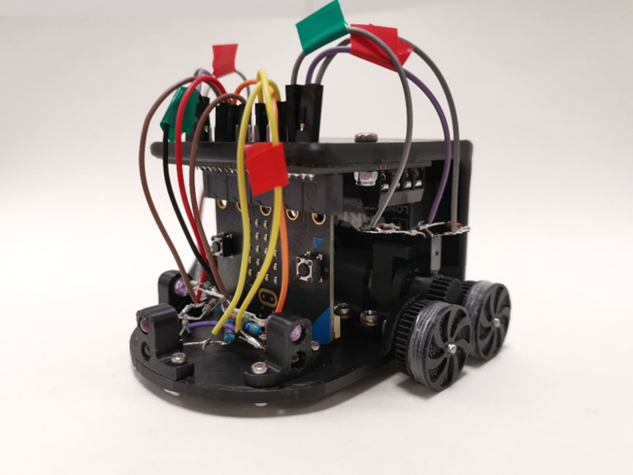
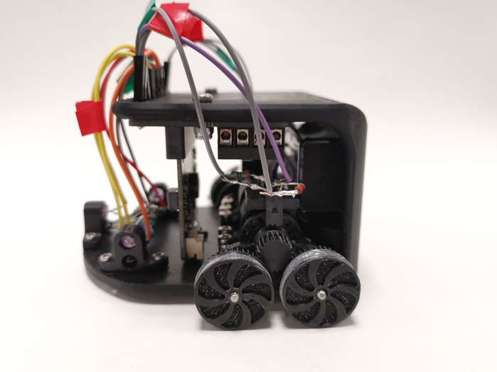
Jeg valgte å flippe Kitroniken og Mikrobiten «på hode» etter godkjenning fra de andre. Dette for å redusere høyden til mikromusa, og at Mikrobiten er bedre beskytta på denne måten.
Et 9V batteri er festa ved at den ligger på en «hylle» på innsiden av veggen, og er festa med dobbelsidig borrelåsteip (takk for spons av denne til gruppe 4).
På drivakselen sitter en motorencoder, og videre en cylinder med tannhjul. Girforholdet her ble 20/40 = 0.5. Girforhold 0.5:1. Det viste seg at motorene roterte mye treigere enn antatt, og jeg valgte å gå for et nytt design for å endre på girforholdet.
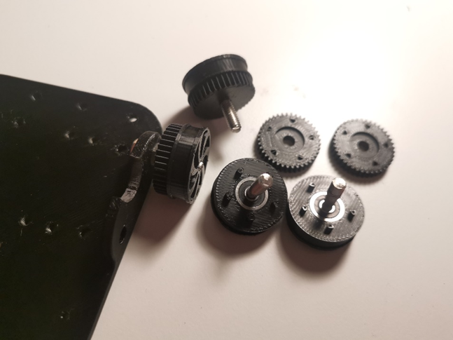
Motorencoder:
Jeg hadde tenkt til å produsere disse i både PLA og kryssfinèr, men jeg har kun fått tid til å teste i PLA.
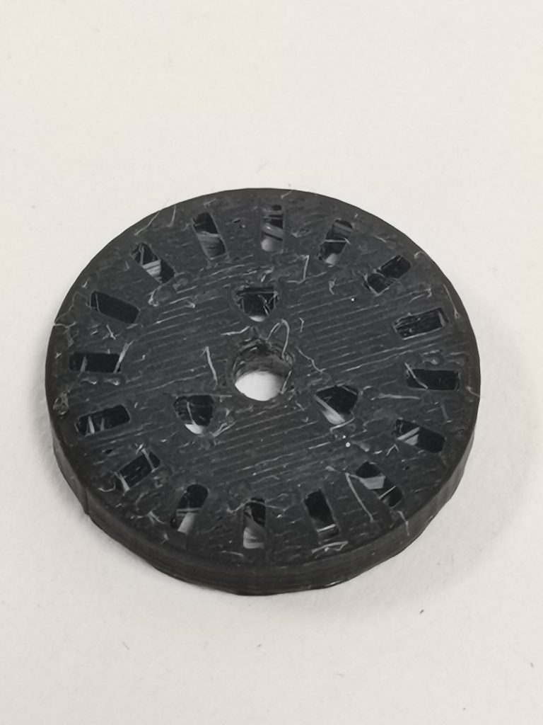
Motorencoder i PLA. Ser en del “stringing” fra plasten, men vi fikk bort det meste før bruk. Den satt godt på drivakselen (etter en del modifiserte prints), og ga tilstrekkelig målinger.
Hvis jeg hadde hatt bedre tid hadde jeg forsøkt å laserkutte en i kryssfinèr også, da jeg tror nøyaktigheten og presisjonen på hullene ville blitt enda bedre.
Hjulene:
Jeg gikk til innkjøp av fire små kulelagere med indre diameter på 3mm. Det var overraskende vanskelig å få tak i en aksling i metall i denne dimensjonen, så jeg gikk til innkjøp av en èn meter lang M4 gjenga stålstang.
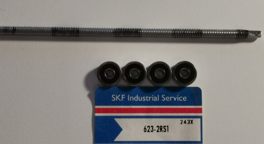
Jeg markerte hvor jeg trengte aksling til kulelagerne, og lengde på akselen. For å slipe ned gjengene og oppnå en diameter på 3mm brukte jeg en Dremel og slipte det ned.
Når fire akslinger var ferdig la jeg de i fryseren noen timer, og deretter presstilpassa de på kulelagerne. Så la jeg disse tilbake i fryseren, og presstilpassa kulelager med aksel inn i hjulene:
Dette var tidkrevende, men resultatet ble veldig bra, og hjulene roterer bra når de er påmontert.
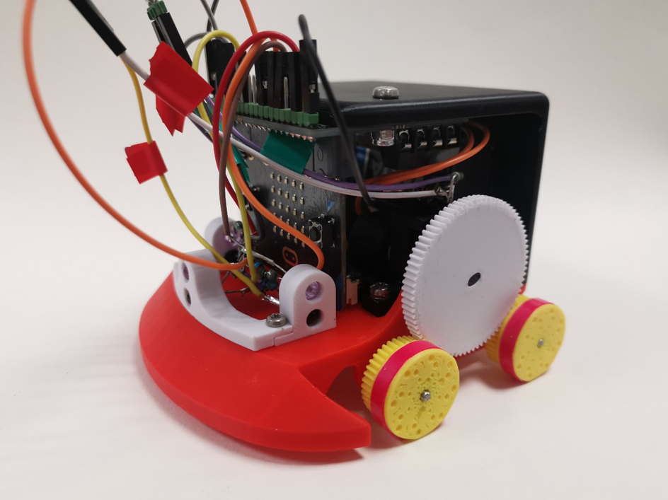
Så gikk jeg i gang på det andre designet hvor hovedformålet var å endre girforholdet.
Jeg la til en støtfanger for å skjerme frontsensoren fra å kræsje i veggen. I tillegg går den foran hjulene, slik at ikke hjulene kan stoppe i skjøtene på veggen.
Lagde nye braketter til sensorene foran, for å begrense antall fester.
Subassemblien under forandret jeg litt ved at jeg lagde flere deler som festes i hverandre for å øke styrken, og lettere å kunne modifisere med for eksempel ulike gir.
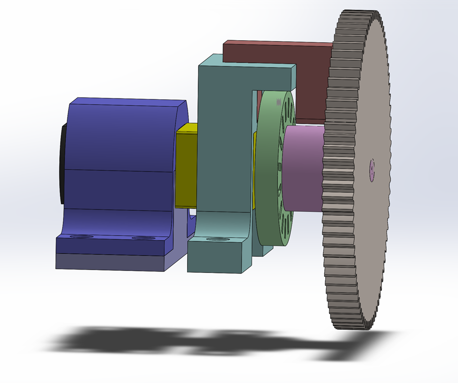
Jeg valgte et gir med 80 tenner som det drivende giret, og hjulene er nesten uforandret med 40 tenner. Dette gir et girforhold på 80/40 = 2, 2:1. Dette betyr at for hver runde drivakselen går, går hvert av hjulene to runder.
På hjulene skulle jeg printe en gummiring i TPU, men jeg har dessverre ikke fått det helt til ennå, da TPU har vært et utfordrende materiale å printe med, og jeg har ikke fått noen vellykkede prints. Jeg regner med å ha fått til vellykkede gummiringer innen konkurransen 29.november.
Felgene er ellers veldig like forrige modell, med kulelager inni, men jeg forsterket festet mellom de to delene felgen består av.
Resultat pdd:
Solidworks filer er sendt på mail til Richard av liten testbane, prototype 1 og 2, og hovedmodellen av endelig design.
Vendel
Week 12 & 13
Weeks twelve and thirteen have been spent frantically trying to finish up the car before the deadline, making all of the last-minute changes to the car design, hoping to have it ready to go. Working on the softest of the software side, I have been struggling to work efficiently towards the goal of having a working machine.
The code of my end, being mostly done in Python to make prototyping easier, had to be translated into Ada, and I began that work without having actually finished all of the work in Python. The missing code has been the smallest of my issues though, as I did not previously have any experience writing Ada code.
During this process, I have gotten more comfortable using AI in my work, having Open-AI’s ChatGPT 4 explain concepts to me, and generating example code for me to try out to learn the ropes. Not entirely trusting its output to be correct or fitting though, I made it a point to only use my own code in the project, and to only use code that I understand the use of myself. Using the AI as a learning tool and a responsive rubber ducky has however been a very valuable endeavor, and I’ve been using it a lot in other sorts of projects since to bounce ideas and analyze my work.
The code is currently not working, and the bot is not ready to solve the maze, but it shouldn’t be far off. Like many engineering projects, finishing on time and within budget is a dream, but not always reality.