Alinur
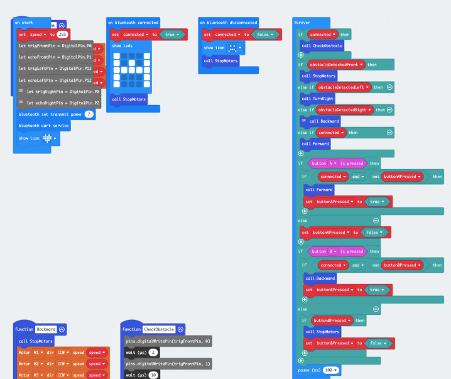
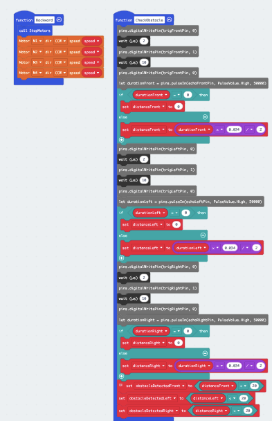
The week kicked off with a deep dive of me working on the ultrasonic sensors on the car. I set out to explore the obstacle detection where the car stops if it detects obstacle and when the obstacle is removed the car continues with it journey. The first thing I did was to initialize the Bluetooth connectivity and set the stage for the interaction between the ultrasonic sensor and the motors that drive the car. By delving into the intricate of ultrasonic technology I examine the basic principle that govern these sensors and what was the magic behind sending and receiving ultrasonic waves, distance measurement and time delays. This was crucial for me to make the car follow the command I send via the Bluetooth app and how it reacts to the various obstacle the car was expose to. The car can move forward via the Bluetooth command and if the is obstacle on the right side of the ultrasonic sensor the car moves backward, on the left side of the ultrasonic the car moves to the right side. If there is obstacle on the front the car stops and wait until the obstacle is removed and it will continue with its journey. Below is the snippet code of the ultrasonic sensors. And a YouTube video that show how the sensors work.
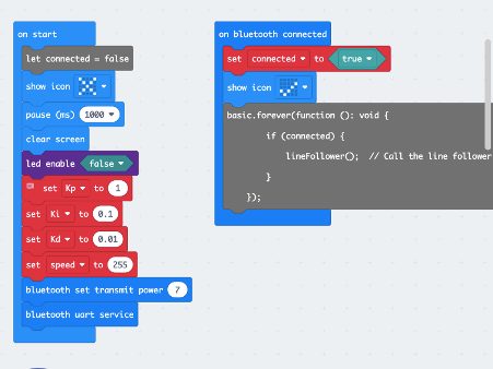
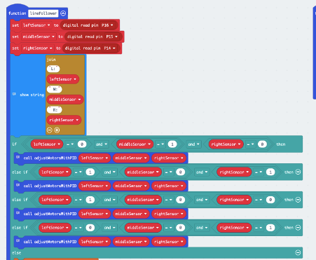
I have also been working on the line following sensor with the help of IRS sensor. The main task of this program was to enable the car to follow a line by detecting and adjusting its movement accordingly. I achieved with the help of the PID control signal that keep the car on the line. I also integrated it with Bluetooth communication which will enable the car to follow the commands from the app. Below is snippet Makecode that illustrate the line following function.
Video for the Control, Ultrasonic and Line Sensor:

Abdirahman
The last couple of weeks I’ve been working on integrating the raspberry pi with the car. I met a lot of challenges; I initially wanted to download my OpenCV code for the raspberry pi camera to micro: bit, and then connect my raspberry pi to the micro: bit. That way both the raspberry pi camera and the sensors could be on the car at the same time. Although the pi camera wouldn’t be the controller of the car, sensors would since they’re directly connected to the motors. However, I could’ve still shown that the pi camera was working as it should by displaying its messages on the micro: bit displayer. For instance, if the car was on the track it would display “on track!”, if it would’ve to turn right “turn right!” and so on. After a had battle (lasting for few days) with trying to find out how to uart raspberry pi and micro: bit, I decided to instead connect my raspberry pi straight to the motors of the car. Hence, the raspberry pi camera controlling the car instead of sensors.
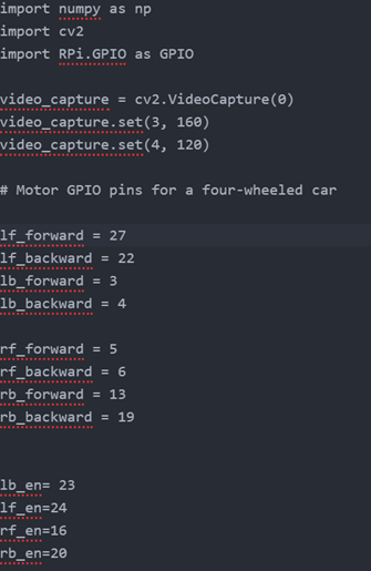
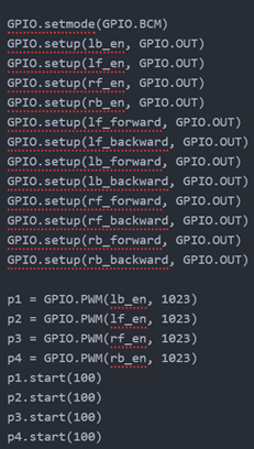
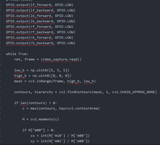
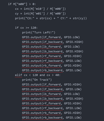
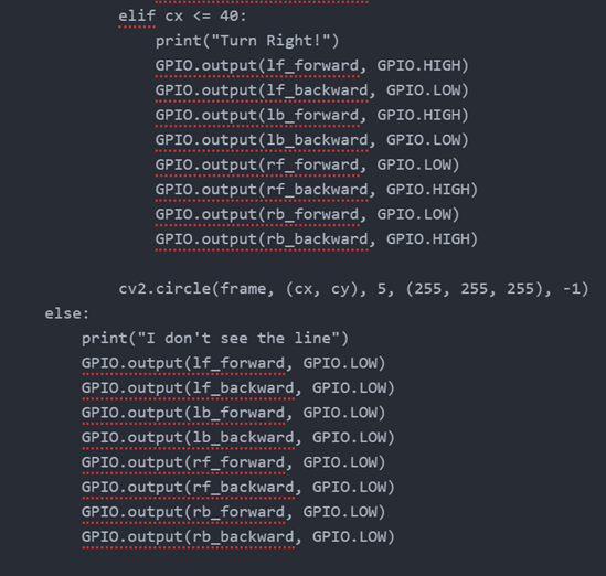
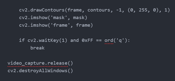
Another challenge that I also faced was that the OpenCV code I firstly wrote was for a two wheeled car. I completely forgot that our car had four wheels. So, I had to modify the code and change it so it could work on a car with four wheels. I had to add new GPIO pins to the new code, as well as expand the if-statements so it works well with the car. Below is the new version of the OpenCV code.
When I was done with all the modifications and change of tactics, I faced one last challenge right before completing the project: the HDMI cable of the raspberry pi defected. Causing the process to halt for a bit.
Videos:
https://youtube.com/shorts/mOEOX2rbHxU
When I put the raspberry pi on the car it worked, but while trying to position the camera, the HDMI cable broke, the code worked slightly but this set us back. I got a new cable but then the SD card was not working making it impossible without a new SD card, I did not have the opportunity to fully show my code working but this is all I have for now. To run my code on a car I would need a new SD card.
Abdiqani
The Simulation work like this, when a button is pressed it writes to the Unity terminal the button that is pressed. When the car drives the text backwards or forward is displayed depending on the direction the car is driving, after the text has been displayed on the micro bit it will then display on the Unity terminal which direction the car has driven.
Video for Micro Bit to Unity Serial communication

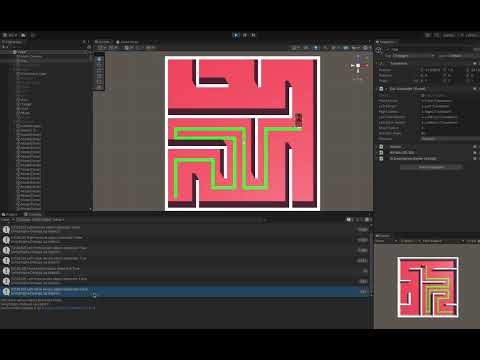
Unity Maze Simulation
Ghebre
Through the past weeks I tried different methods to approach the right algorithms that I could use to automate the steering system of the autonomous car. At last, the autonomous car is driving as designed, as we see on the videos.
I used this scheme (see below) to make the autonomous car drive to different directions. The scheme has almost all possibility of how to navigate a four wheel, each wheel has motor that drives into two directions forward and backward. 1
This project started as a group project with the perspective of having all members focus on integrating the car. But later the assignments were divided by the main teacher and given to each other. Coding the microbitv2, Bluetooth control, Camera and Simulation. Then afterward I focus on coding the microbit to make the car drive by following lines, sensing the environment, and make it as fast as possible. But that does not stop me from trying to get to know what other were doing.
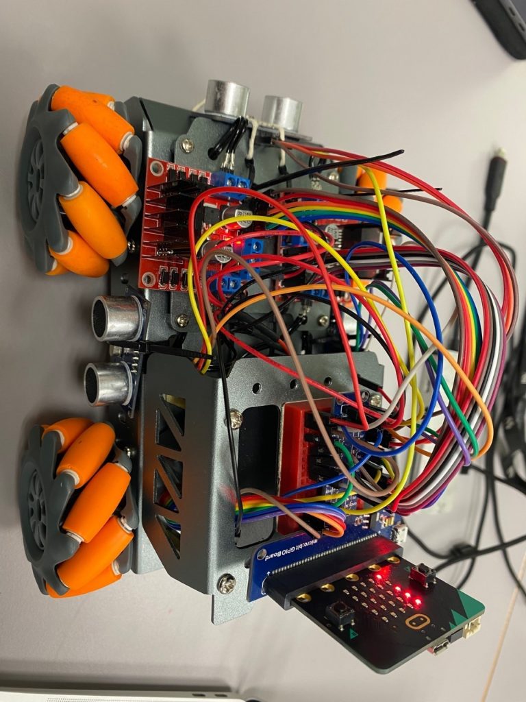
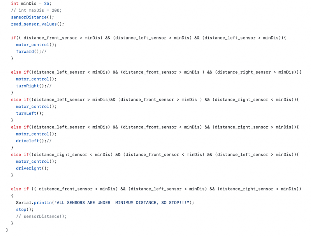
The car has four wheels and four engines and two different type sensors and other components. The IR sensors and ultrasonic sensors. I used three IR sensors which detect white and dark, 0 and 1 respectively. The car follows the line using three IR sensors which are place at the front under the car. They are at the left, right and middle. Using the conditions of the three sensors the car drive to its destination. For safety reasons the car has the ultrasonic sensors which are used to let the car see its surroundings. The ultrasonic sensors are also used to navigate the autonomous car when it is out off the road. You can decide the distance the ultrasonic sensors use for decision making. I used 25cm as a minimum value, but you can change that for example to 5cm and make the car decided upon the result it get from all three sensors.
IR sensor conditions
.
Ultrasonic sensors condition
PID
The Proportional term responds to the current error, which is the difference between the desired speed and the actual speed of the motor. This term contributes to the immediate correction of the speed error. The integral term considers the accumulated sum of past errors over time. This helps eliminate any steady-state errors that may persist, ensuring that the motos reach and maintain the desired speed over the long term. The derivative term accounts for the rate of change of the speed error. It helps dampen rapid changes in the error, providing a smoother response and preventing oscillations. Then the output of those three components is used to adjust the power supplied to the motors. Then the PID controller calculates an output based on the weighted sum of the P, I and D terms and this will be used to adjust the power supplied to the motors. The adjustment to the motor aims to bring the actual speed closer to the desired speed. The speed of the motor is continuously monitored, and the PID controller adjust the motor power.
Through this project I learn more about autonomous vehicles and the power of microbitv2 and how to make a smart system combining and integrating the different part. I was happy with the team, and we work mostly together.
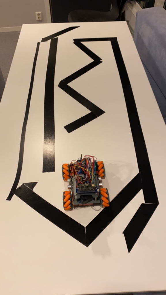
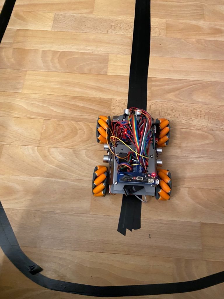
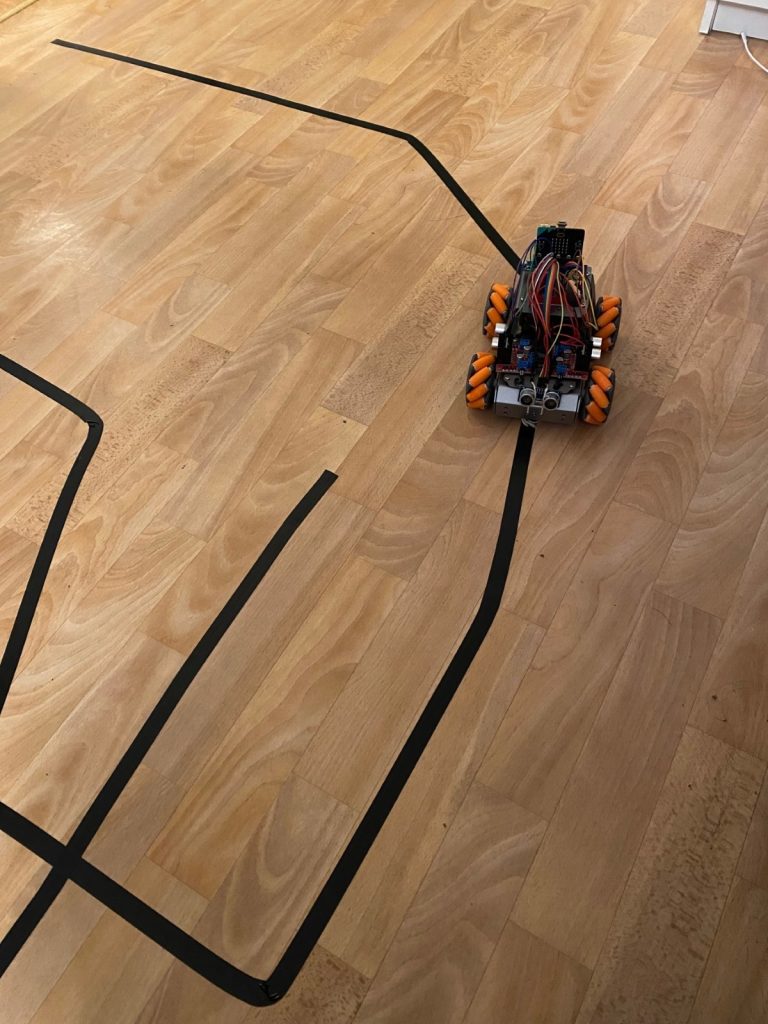
Costs: I had to change batteries every time I use the high speed. It gives me indications on low battery by stoping the other two motor. When I am at home, I had to tape the living room with black tapes and sometimes over the table when I am troubleshooting, as you see on the pictures.
GitHub: Some of the codes that are used in previous posts, are not in GitHub.
https://github.com/ghenzebu/AutonomousCarG5-/tree/main
YouTube link: those video’s show the changes from start to finish.
- https://youtube.com/shorts/RCHeWANcq1s
- https://youtube.com/shorts/xqudLzDpkV4
- https://youtu.be/ecz9_ISEMLU
Pictures: that are taking at my place