Doomsday is soon upon us… 🤯
Can we go the distance?😳
Will the MicroBros reach the sweet sweet center of that maze?🤤
Most importantly, is there time to add googly eyes?🤓
Final video
NOTE: We use external power as currently, there are issues when the motor driver and Micro:Bit are not both connected to a power source.
Code
All our source code is publicly available at: https://github.com/MicroBros/MicroBros
Individual contributions
- Jonathan
- PID-controller implementation
- PID-controller applications like regulating left-right and rotation to drive straight
- Tile detection logic using IR sensors
- Implementing methods to find minima, maxima of distance readings including filtering distance readings like Moving Average (now deprecated)
- Experimented with accelerometer-based position tracking
- Assisting Mats with debugging, tuning and theorycrafting
- Mats
- Setting up project structure with CMake, debugging, custom lightweight toolchain for MicroBit v2 using CODAL
- Manage project planning and roadmap through Kanban and milestones on Jira
- Implementing the core libraries with data structures for maze, directions, algorithms, logs, serialised data structures and other common utilities
- Creating a desktop-based simulator for algorithms that can also remote control the device over BLE
- Write custom drivers for the DFR0548 (I2C motor driver), HC-SR04 (Ultrasonic, uses interrupts) and IR using the ADC.
- Implement the signal processing pipeline for IR (Lowpass, bandpass, etc.)
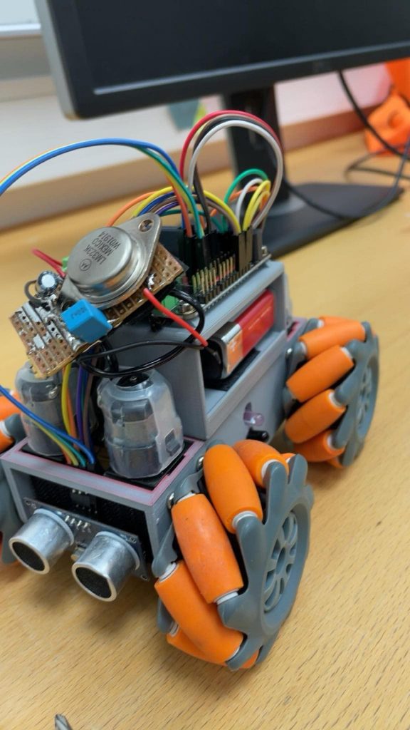
- Create the state machine and main loop for the robot
- Implement BLE services in the firmware to both control motors manually and control the state of what algorithm being used, manually step, start/stop and more
- Implement a custom C++ timer wrapper using lambdas instead of directly setting up CODAL messagebus events.
- Iver
- Research and documentation on the flood fill algorithm
- Researching, planing, testing, soldiering and physically implementing the IR sensors
- Research, planing, testing, soldiering and physically implementing the batteries. Sadly these does not work at the moment. Hopefully, I can get them to work before 29th of November
- Generally trying to fill the place of our missing mechanical and electrical engineers, as my fellow microbros can program at such a high level that I am way more helpful focusing on hardware
This (final) week of progress blogged ❤️🔥
Jonathan 🧙♂️
This week’s been all about spending hours and hours making turns go smoothly since this is what we suspect to be the last missing piece in completing the challenge. Since we can’t sense anything diagonally, we can’t really use sensors to regulate turns. Also, since the MicroBit compass doesn’t reliably work when the MicroBit is placed vertically we can’t use the compass. Therefore we are “hard-coding” our turning method by explicitly telling the motors what speed to go in and for how long. The idea is We’ve also made the speed of the motors a function of time to further smooth the turn. Below is a slo-mo video where you can see how the turns look:
Mats 🧑💻
Turning has continued to be the big time sink this week, driving forward with at least one wall adjacent works perfectly as we have reliable IRs on the sides at a high sample rate used for PID controlling strafing and rotation. None of our sensors however are reliable when turning as we have ultrasonic alternating every 28ms (Seems to be stable, since we always hit a wall inside the maze).
With an ideal design we would have been able to rotate in place meaning we could ditch having to be able to drive both ways and have a better sensor setup on one side, with it being IR only. For now we need to do the best we can with what we have. This could have been done by using smaller mecanum wheels that could have been 3D-printed, however this requires expertise our group lack.
For what we have, adding an 9-DOF IMU like the BNO055 would greatly enhance the ability to keep track of direction. If we get a single turn wrong we currently have no reliable method of detecting it, meaning the robot will assume it finished the turn and the tracked position will be off by 90 degrees and all further movement will be incorrect.
Remote debugger finally working! 🎉
The remote debugger is finally working and was useful to let us iron out some position related bugs! Here’s a video:
Random freezes 🥶
Another issue that we noticed during this week is that the robot would finally just stop evaluating the main loop and get stuck moving and stop sensing, first I assumed it was BLE related and disabled the entire remote debugging stack, however it still happened. After that I started running with step-based debugging letting me pause on those freezing to find out what the MCU is up to, turns out it gets stuck writing to the motor driver on the I2C bus. Interestingly Errata 219 for the nRF52833 informs that the timing specification in I2C is violated at 400kHz which is the default bus clock speed with CODAL. However it applies the workaround listed to set it to 390kHz. Seems like it may not be perfect, I changed the bandwidth to the other standardised clock speed 250kHz and only write the PWM speeds when there is a speed change. This seems to have mitigated all the random freezing.
Ghost walls 👻
During testing the robot would at times detect a wall in front of itself when there was none 😶🌫️ , I ended keeping track of the previous ultrasonic reading too and also checking that one with a slightly higher threshold. This seems to have made detecting walls in front and back way more reliable.
Reflection 🪞
Based on the prerequisites we have had throughout the project period: starting with a robot that did not fit (Thanks for the help Richard!), and doing work that would better fit electrical students, we have still managed to get something that works (some of the time).
There are certainly things that I have learnt during the project period which I think would have made the result quite different if I would to attempt a project like this again, like spending more time on downsizing, maybe creating a custom PCB and not use a 3D-printed chassis, and having high sample rate data on distance and orientation.
In the end our focus ended up just being attempting to achieve reliable movement, lowering the already slow speed, tweaking a bunch of constants, and more as we largely hard-coded turning with only some basic sensor data being used to end the turn within a small interval.
Iver 👴
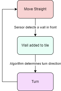
This week I finished the battery pack. I went with the original plan of using the LM323K voltage regulator, with two capacitors and a 9V battery.
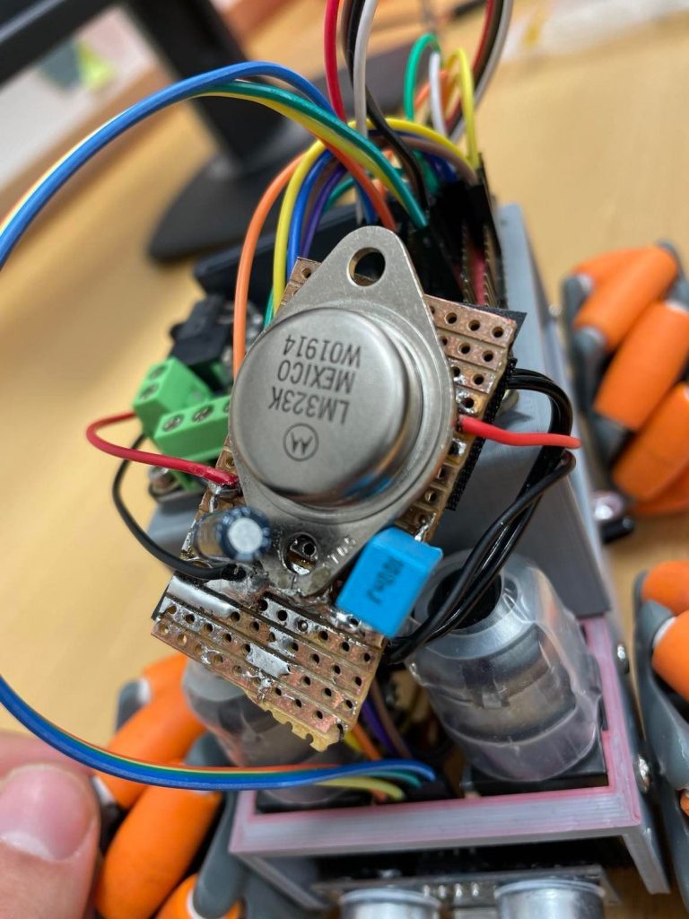
The car worked great, but it needed a separate power source for the micro:bit itself for the sensors to work properly. For this I will use a micro:bit battery pack for 2XAAA batteries that I have at home. As the same thing happened when we hardwired 5V we are all but certain that this will do the trick.
Sadly this system did not work. The sensors does not work properly while the car is driving. Therefore it hitches and crashes a lot more than normally. Our theory is that the battery either is not giving a stable enough voltage or that we cant pull enough amperage for the motors and sensors. I have some ideas for troubleshooting. And I have some Panasonic Eneloop Pro AA batteries that I think may work. But I will have to see if I have enough time to do this. The car is in use on the maze most of the time as well, so Im not sure if I am helping or in the way if I do this.