For the final “official” week of project work we conducted the following efforts:
Discipline – Software:
GitHub link:
https://github.com/asklindbraten/2023Gruppe4-Micromouse.git
Erik-Andre Hegna:
This week has been an eventful week. It feels like I’ve been to hell and back again. As we have done a lot this week, this blog post will try to cover the details as best as I can. I will not always cover the events in days, as days are mixing into each other, but focus on how we progressed through the week.
This week I have worked a lot in combination with Lars regarding the calibration of different functions and sensor values, while Ask has been designing the algorithms and helping us on the side.
The week started optimistically. Last week we got the PID controller running smoothly in between walls and the basic mouse-turn functions working.
I started the week by trying to fix last week’s problems. As we no longer could trust sensor values further than 1 cell ahead. I started testing different intervals that the sum of right+left sensor values could fall into. I noticed that every time the micromouse was driving through 2 columns, the sum increased to values between 7.5 and 10. The rest of the time it usually stayed under 7.5 Seeing this, we tried to implement this in combination with the PID-controller with decent success. Finding another way to find differences between cells was a relief.
As the PID controller was making the micromouse move smoothly between cells when going forward, our next step was to make it able to make turns. As the micromouse started sensing longer distances to either left or right side, we noticed that making a turn as soon as it “sensed” distance was not possible. 10/10 times it crashed into the column between the cells. We figured that it had to move forward for a certain amount of time before making the turn. As an easy solution to this, we hard coded into it that every time it sensed an open path to either side, it should drive forward for a set amount of time before making the turn. With loads of calibration, we got it to move into one cell, make a turn, and move forward into the next cell fluently and consistently.
As we now got a working PID (when there were walls on both sides), the mouse could make turns, and sense column separation between cells. We then implemented a simple 180 degrees turn (turn 180 degrees towards the right if there was more space on the right side to make a turn, and vice versa).
Everything was going smoothly until late afternoon Wednesday, where we managed to fry the microbit when the voltage-supplier cable (coming from an external power-source) managed to touch the USB the microbit was connected to. We quickly replaced the MB with a new one, and it seemed to work OK again. After lots of testing we noticed that the program started to bug. More and more often. The mouse could be running smoothly for 30 seconds, and then suddenly get stuck in one of the motor-drive functions. We were problem testing approaches like counting how many sensor-values we could measure before the program bugged. We used millis as a time counter to check if there were some time issues. Or if it was running out of RAM. As we tested these different things, the problem only got worse and worse. We managed to find out that it could read sensor values indefinitely, but when it was reading sensor-values at the same time as moving forward(motor-functions in combination with sensor readings), we were only able to use each sensor about 90 times before it bugged out. This number was consistent. We teamed up with Steven to ponder on what the problem could mean. We concluded that the motor controller hadn’t been ruined when the microbit got fried, but it had been severely damaged to an extent which made it unable to function properly.
By our next session: Lars, Steven and Hugo had done a phenomenal job of replacing the old motor-controller board with a new one. As it was a newer version, we had to replace all motor controller Arduino code with Ada language. Additionally, the micromouse, which previously was running on 9V, was now running on 5V. The voltage reduction gave the mouse a speed reduction, which in and of itself is not a problem because we gave up speed long ago. But we had to alter all motor functions, PID-controller, and our hardcoded turns. The speed of the motors was also now working as digital, and we did not have the time to learn how to make it analogue with Ada-language.
So, Saturday morning we started fixing and recalibrating everything to make the mouse run as smooth as it did before the motor-board change. Most of the day went to this work. Sunday was the big day as we were now ready to merge all motor-code with Ask’s massive object-oriented maze and micro-mouse classes. The merging went smoothly and had few errors, but we had to design the choice-based turn logic where classes and motor-functions could work together to be able to map the maze. We also had to construct the main loop. Everything seemed to be working smoothly as we compiled the code onto the micromouse and we were ready to test everything all together in the maze. “Victory music” was played to set the mood as the micromouse was supposed to move perfectly through the maze. We felt like champions. The great irony of it all was that of course, once we pressed the “run button” on the mouse, it stood still. Nothing happened. Nothing at all. I don’t want to go into detail of the frustration of this, but we sat until 21 (6 hours) in the evening troubleshooting this problem without success. As the deadline for the submission was the next day, and we were tired and stressed out, we figured we wouldn’t be able to get anywhere. We instead made everything ready for submission.
In retrospect as I write this blog, a few hours before the deadline, I feel both defeated and victorious. It really sucks investing so much time into a project and not making it work as intended. But I have learned a lot about the importance of documentation, setting deadlines for progress, sensor and motor calibrations, coding with a system mind-set, and the importance of understanding logic and theory before coding. Working interdisciplinary has also been a fun and challenging experience.
Lars Leganger:
The final week of the project is here, and it was an eventful one to say the least. We started on Monday to go through the plan of what needs to be done by weeks end and started to work out the movements for the mouse in the maze. We ran tests to se how well it moves and kept adjusting the moves of the mouse until we had them the way we wanted them. We tested the sensor to see what value we get when its between two point and it was higher then the walls. That was the creation of the wall counter.
The job was the same on Wednesday. We tested the left and right turn as well as the 180-degree turn. One of the problems we worked on was the mouse’s ability to pick up the tags of each cell in the maze as it struggled to detect them when it did a turn or rotation in a cell. One solution I tried was to also count when it does a rotation or turn but it didn’t work the way I wanted it to.
On Thursday we started to face some very unforeseen problems. The mouse’s movements were no longer doing what it was programmed to do. It would not drive the way we set it to drive and it suddenly stopped for no reason. I started on a very extensive search for the problem. Stripping down the code and function to the very basic functions. At one point all we had it do was drive forward and it could not do that right. At first, we thought that it might be a memory issue since it suddenly stopped reading sensor values. I tested the reading function by timing it and tried to add on driver functions to see if things changed. The outcome was that it was able to read for a long time without driver functions but when the functions were added it wouldn’t run more than 30 seconds. The search continued until the conclusion was that the driver board was fried. We came to that conclusion because we managed to fry two Microbits by letting the power supply touch the USB port. Thus began our hail-mary attempt to save the project.
The first thing I did was to ask for a new driver board from Steven. Unfortunately, he didn’t have the same driver board that we used so we had to adapt to a new one. The new driver board could not work with our current motor driver library but thankfully Steven helped us to implement a new one. It gave us the ability to move again but it came with a set of new challenges.
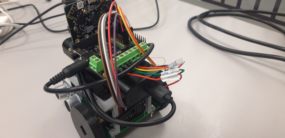
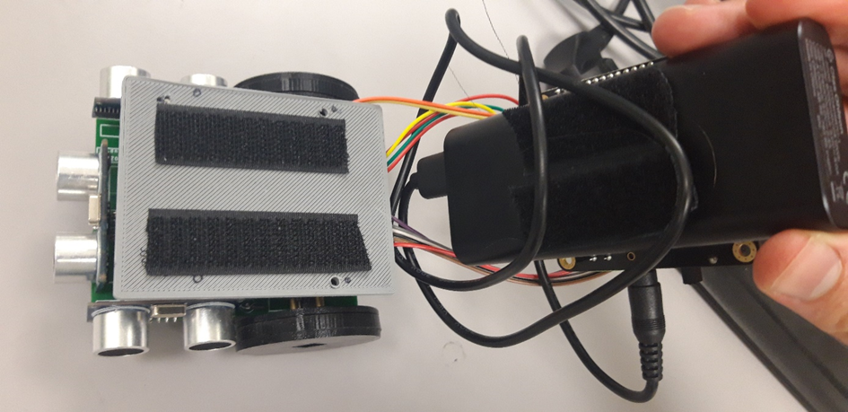
For the mouse itself we needed to use a new power supply. Luckily, I had a power bank we could use. I took the power bank and used Velcro to attach it to the mouse and then more Velcro to attach the driver board. It worked well. The power bank ended up being faulty, so we bought another one and did the same.
The second challenge was the loss of speed and regulation of speed in the new motor driver library. This meant that we no longer could regulate the speed which we used in the left and right strafe functions that go in the PID controller to make better adjustments to the center of the maze. Also, all our hardcoded turns and rotations needed to change because of the change in speed. For the strafe function I tested to see if we got a similar result if we just activated one wheel instead of both as we do in the normal turn function. That gave a better result than using both wheels.
The third challenge was to get each component back up and running. The sensors did not read even though they were connected to the same pins as before. Me and Hugo changed the pins and tested different combinations until all sensors were reading again.
Saturday went to testing, testing and more testing to get the mouse back to drivable form. The functions that needed an update were the cell counter, driver functions, turns and rotations. All the functions for driving and maneuvering were updated to match the new speed and the lack of speed regulation.
Sunday went to integrate the now new and improved driver functions with the maze solving algorithm. We started to look at all our functions and worked out the algorithm. We started by looking at every situation the mouse can end up in and gave it direction to drive and when it should look for a path not taken. The factors we had to take into account were the position of the mouse, whether or not the cell next to it was visited or not and what driving action we wanted to prioritize if the mouse had multiple options.
At the end of the day I took a video of the mouse driving in a maze we created.
Ask Lindbråten:
This week was full of ups and downs, and a lot of surprises, as many of the group members have described, and although some of the time has gone to important discussions, and participating in overlooking testing, my main job for this week was to finalize the maze-mapping algorithm and fully integrate it with all the necessary motor functions. In light of the discovery that we couldn’t fully trust sensor values beyond 1- 2 cells or squares (as identified in week 12), we had to abandon the solution that relied on division of the left, right and front sensor values to calculate positioning within a square and determine the number of visible cells to the micromouse in each direction. This was pretty unfortunate as we thought it worked well in theory, and I think we were all pretty happy with the solution.
However, tweaking it wasn’t much of a hassle. The creation and connection logic remained the same, but we had to update the active cell the micromouse was in with only one neighboring node in the direction where the respective sensor value was higher than a set limit. After that, I worked with adding additional functionality to the appropriate classes, for instance: adding a function to print the node-network, changing the maze constructor to handle every number of rows and columns, adding a function to change the active cell the node is in based on position, adding an extra condition to the createAndConnect() – functions to prevent reconnection of already connected nodes/cells, changing the isGoal()-function to work with member-variables instead of hardcoded data, and limit the use of local variables to optimize memory usage.
After that, I was finally down to start integrating the motor-functionalities. Erik and Lars had already designed most of the needed motor movement functions, so with some minor tweaks like adding an update of positioning to every hard-turn and dead-end rotation, and adjusting the basic forward(), reverse() and righturn() – functionalities etc. to operate properly with the new “dfr0548.h” library (Lars gave me a good understanding of how to do this), we were pretty much setup. All we were missing were the basic movement decision function, when entering a square with one or two open paths, based on sensor data and the node network. Lars and I started to work on the theory and logic behind every scenario we could encounter, where an important decision to turn or drive forward had to be made. After some time, we quickly realized that the function would require a lot of hardcoded if-tests to adhere to every scenario, so Erik came up with a better idea that could reduce the redundancy and we sat down to develop it. The idea was to update a vector with three elements, where the first element would represent what’s in front of the front sensor, the second element would represent what’s in front of the right sensor and the third element would represent what’s in front of the left sensor.
We managed to narrow each possible scenario, to what could be “in front”, down to three different scenarios: the first one being that a path is open and the next cell in that path is not visited (value: 0, would be added to the vector), the second one being that the path is open, but that the cell has been visited (value: 1, would be added to the vector), and the last one being that there is a wall in front, so the path is closed (value: 2, would be added to the vector). The code logic for this functionality and additional comments can be seen in the updated_visited_dir() – function (“dir” for direction) in the main.cpp file on GitHub. The actual “make movement decision” function would then use this vector to either drive forward or make a hard-right turn, a hard-left turn or a dead-end rotation. The function was structured, to account for the first open path where the next node had not been visited and call the appropriate motor – function to enter that cell. Here’s the code for a more visual understanding:
//Developers: Erik/Ask.
void makeMovementDecision(){
   //A list of appropriate choices. 0 means open path and not visited. 1 means path but visited. 2 means wall.
   //We want the micromouse to make choices based on the visited_dir (visited_direction) vector. the value: 0 has priority over the value: 1 etc.
   //First element = forward action, second element = right turn, and third element = left turn.
  if (visited_dir[0] == 0){ //node forward not visited.
    forward();
  } else if (visited_dir[1] == 0){ //node right not visited.
    hardRight();
  } else if (visited_dir[2] == 0){ //node left not visited.
    hardLeft();
  } else if (visited_dir[0] == 1){ //if all nodes visited and no wall forward.
    forward();
  } else if (visited_dir[1] == 1){ //if all nodes visited and wall in front.
    hardRight();
  } else if (visited_dir[2] == 1){ //if all nodes visited and wall in front and right.
    hardLeft();
  } else if (visited_dir[0] == 2 && visited_dir[1] == 2 && visited_dir[2] == 2){ //all nodes visited and dead-end.
    deadEndLeftRot();
    deadEndRightRot(); //in case the other rotation function doesnt trigger and vice versa.

  }
}
In other words, if there is no open paths/or the next node has already been visited forwards, it would check the right direction for open paths and an unvisited node. If there is no open paths/or the next node has already been visited to the right it would check the left direction etc. Furthermore, it none of those if tests were entered it would check each index of the vector for the value 1 and conduct the prioritized movement based on the first “1” it can find. Lastly we added an additional if – test to account for the possibility of encountering a dead end. Since the dead-end rotations also accounts for the ratio between the left and right sensor (inside the functions), we need to call both of them to make sure one triggers.
After we developed the above functionalities, the last thing remaining was to setup the void loop() – functionality with the right function calls, variable updates and if-tests. This took some time and discussion but after a while we were ready to start running the final maze tests. We were all pretty excited, but was quickly let down when we saw that the compiler stopped running before the creation of the smart pointer objects (the smart pointer objects was declared at the top of the main.cpp). As seen in the picture below:
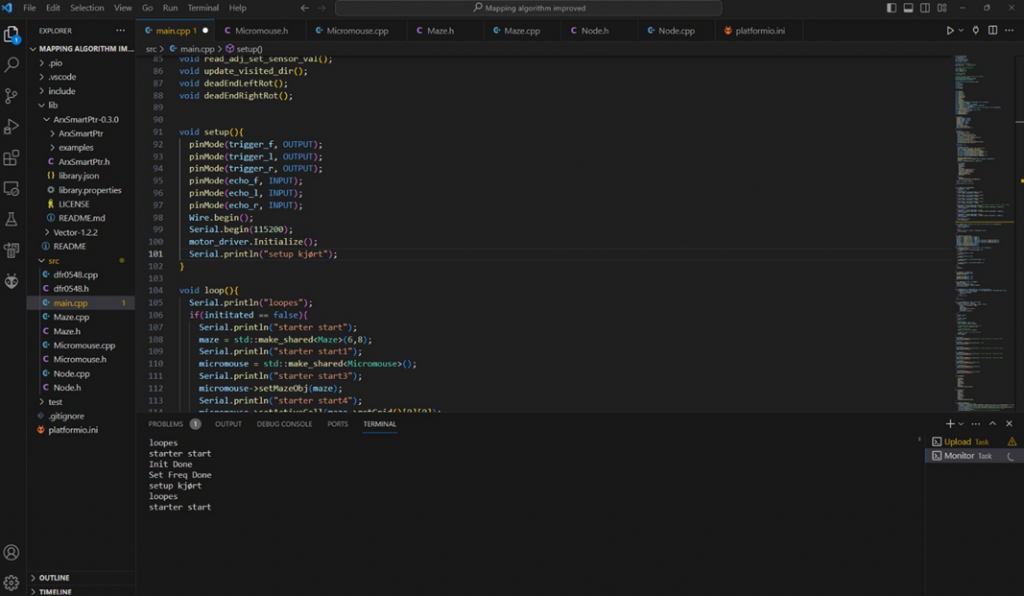
This bummed me out deeply, because I feel like I could have discovered it at a much earlier point, by just creating some test objects and see if I were able to create- and call member-functions on them, and then had time to change out the smart pointers for raw pointers. But it didn’t even cross my mind that this could be a potential issue as the description of the library fully indicated that it would be suitable for arduino/PlatformIO, and I had no issues when building and uploading the class builds to the Microbit.
Although it really sucks that we couldn’t get every software part to interact efficiently together, I’m still glad that we at least have the necessary motor code to maneuver in the maze autonomously based on sensor-values and a cell-counter (called wall_count in the final code). Working with an interdisciplinary project has been both challenging and fun. I’ve increased my experience and skills with object-oriented programming, learned the importance of testing and calibration subcomponents thoroughly and how much time this requires, as well as coding while envisioning the bigger picture and the system as a whole.
Discipline – Electrical:
Hugo Valery Mathis Masson-Benoit:
The last week of our project gave us some surprise in the end. During some tests run by the software engineer, some Microbit cards were permanently damaged, and the board was fried. Due to this and the fact that we cannot order the same board, we needed to improvise.
On the advice of Steven, we chose to replace the original Microbit board by a Microbit Driver Expansion Board. This change meant three things :
- We can no longer use a 9 volts battery to supply our robot. Due to lack of voltage regulator integrated in the new board, the only input viable to use directly for the whole project is a 5 volts battery pack.
- A change in the code for the motor driver (something that is going to be covered in the software part).
- A little adaptation of the mechanical structure due to the new battery size and MCU.
Hardware impact and modification:
The change of the MCU does not invalid the use of our PCB, however some changes needed to be made to allow us to continue using it.
Because we were using male to female wire before, i changed all the old wire to replace them with new female to female wires. This allowed us to connect the PCB directly to MCU with the benefit of a cleaner cable management, due to most of the wires being still attached together.
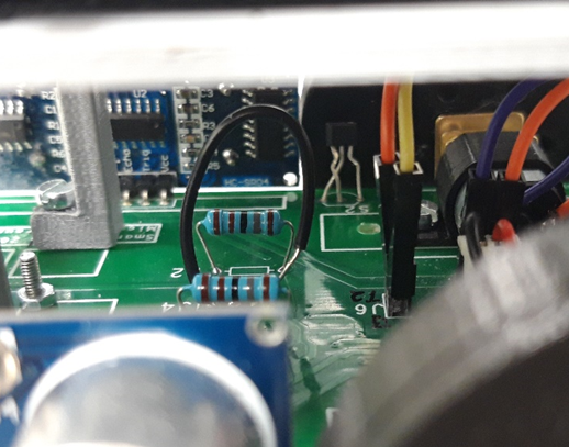
The main problem concerning the PCB is the fact that it had a voltage regulator in it to convert the 9 volts of the old battery to 5 volts for the different sensor. So, I removed it completely, I cut it and replaced it by a simple wire. This way, the Micromouse stay the cleanest as possible (considering all the change it went through so close to the end), and we can use all the sensor with the same battery as the MCU.
The biggest impact of all those change on the performance of the Micromouse is that the motors will be powered by 5 volts, making them slower. Despite this problem, we all agreed that it’s better to have something that works slowly than having nothing. So, it’s the solution we chose to adopt.
To cope with the change of the size of the power supply, we used some Velcro to fix everything together. The good point of this solution is that we can easily access and remove the battery, while everything is well fixed.
I also helped the software engineer resolving a problem concerning the attribution of the pins to control the ultrasonic sensor. This will be covered in the software part of this week blog.
Pspice simulation:
During the conception of the electronic design, I didn’t go through the process of a Pspice simulation to verify that the design with the ultrasonic sensor was working. I did not do that because I tested everything directly on the breadboard in cooperation with the software engineers when I was creating the design.
After talking about this with Steven, I realized that despite the design working accordingly to what was intended, it was an error in the methodology to not simulate it.
So, to be able to prove that the design works and that the power is enough to supply the Micromouse, I simulated it on Pspice.
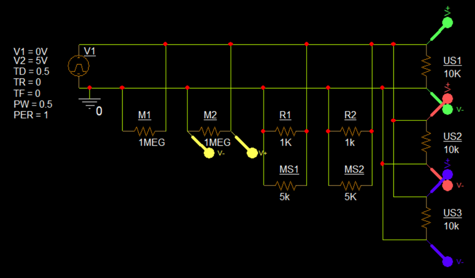
I used a PWM voltage supplier to simulate impulse from our battery pack, and some resistors to simulate the different load of the component of the Micromouse.
M -> Motor : 1 MEG Ω
MS -> Magnetic sensor : 10K Ω
US -> Ultrasonic sensor : 5K Ω
R -> Resistor : 1K Ω
The result of the simulation gave me a clean 5 volts for every component.
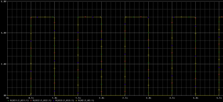
This simulation shows that the supply of every component is assured by the 5 volts battery pack. I can now say with simulation data that the 5 volts battery pack is sufficient to supply our whole Micromouse.
Conclusion:
This last week was full of surprises concerning this project, but I’m happy with how we handled it. The electronic part is working well, and has some simulation data to go with. Now the last thing left to do is to put every documentation/project file on GitHub/the USB stick, and work on the final presentation.
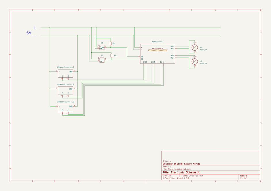
Jemima Niquen Tapia:
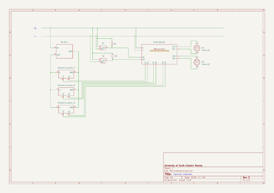
This last week I have done the schematic of the final circuit we had. But unfortunately, we had to change it in this few days as we had a problem. In the first picture we see the first version, and in the second one we see the last and final version of the electrical schematic in the micro mouse. The main difference is that we have taken out the regulator, and that mean to change the battery from 9V to 5V, that way the sensors are powered as they have to. Also, we have change the motor board, it will work the same, the only change is that as it’s powered at 5V the motors will go slower.
Discipline – Mechanical:
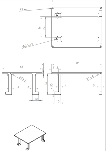
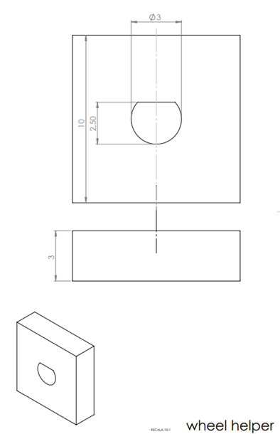
Cesia Niquen Tapia:
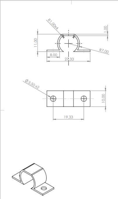
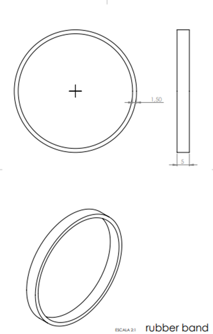
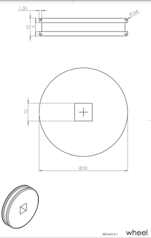
This last week we finally know the elements of the structure we are going to use. So I’ve done the CAD drawings for these pieces. These pieces were made and designed to solve the specific needs for our micromouse, so all the sizes are according to this.
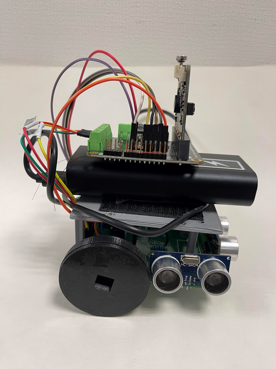
Video of maze navigation:
Final pictures of the micromouse: