Final videos
As we approach the final week, most parts of the system are finished. Like the previous weeks, this week has focused on testing and benchmarking the system.
We’ve done some safety tests with different backdrops and found foam packing insulator to be a good fit. The foam is light enough to allow some penetration of the projectile – so that it doesn’t break – but firm enough to stop the projectile with one segment.
Hannes Weigel
Raspberry Pi Touchscreen Box
We use a touchscreen as part of our interface to the Raspberry Pi 4, we needed a more suitable enclosure since the display ribbon cable is quite fragile.
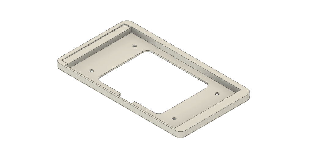
This is plate that mounts onto the backside of the touchscreen giving it some shielding for the internal components.
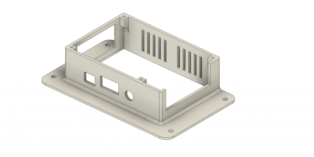
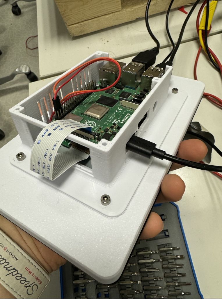
To make the entire package more transportable, an enclosure for the actual Raspberry Pi is screwed on the backside of aforementioned plate.
Christopher Daffinrud
In this final week of our system before posting this last blog post, our focus was around testing and finalizing the Turret System. The videos are posted at the top of this blog post. I also made some adjustments to better accommodate the end product:
Resize GUI for Pi Display:
One adjustment needed was to resize the Tkinter GUI to properly fit the Raspberry Pi Display. Since the GUI doesn’t automatically adjust widgets and the camera feed for smaller screens, I needed to make adjustments and manually resize different elements in the GUI class to properly fit the Raspberry Pi Display.
12V to 5V troubleshooting:
I collaborated with Mats and Harald as well this week, addressing issues related to our 12V to 5V converter.
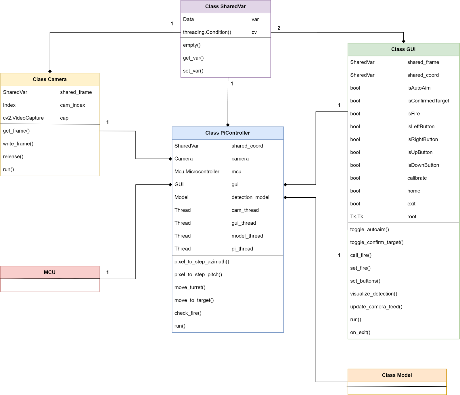
Iterating on our Class Diagram:
In response to changes introduced during the implementation of motor control on the Arduino Nano, I revised our class diagram. The updated diagram reflects alterations in member variables and the connection between the PiControll class and communication with the Nano.
Documentation for Doxygen:
Ole and I utilize Doxygen for documenting our classes and functions. I spent some time this week to ensure proper documentation, especially in classes I have done most work: PiController, Camera and GUI.
Here is a link for a PDF with our software documentation:
Mats Bergum
Unfortunately, the Raspberry Pi would not boot correctly. Thus, some time was used to find the problem. First, we thought that the problem was in the regulator I manufacturer. However, I later found out that, for some reason, the Raspberry Pi would not boot using the power pins. So, by routing the power through a USB C, it finally started properly.
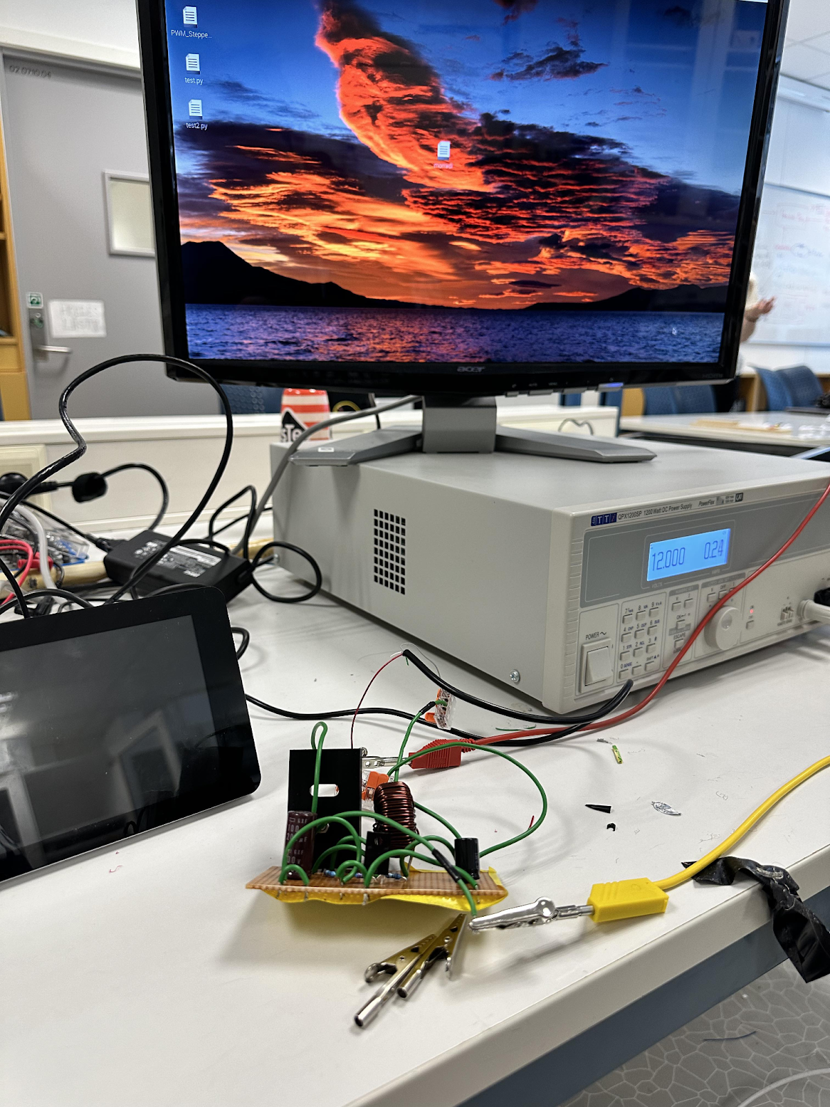
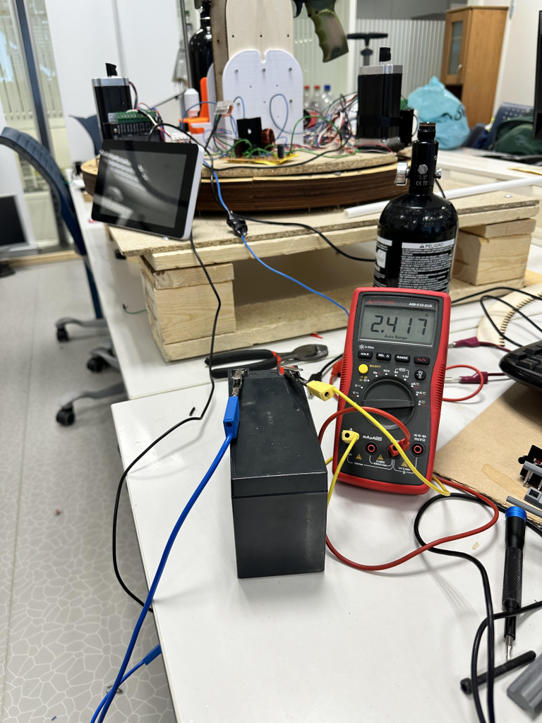
After resolving that issue, I could finally power the complete system from battery power. It seemed to work. However, when trying to use the motors, it was apparent that the battery we had acquired could not meet the power demand. With the tight schedule, getting a battery with the necessary capacity will not be possible.
Harald Berzinis
What a week! Started this week with tidying up the trigger mechanism wiring, and rewiring to match the new pins. We found out that we could not use a single nano for controlling both the trigger mechanism and the motor controllers, this is due to the library for motor control and servo started to interfere with each other. The solution for this was to use two nanos dedicated for each task.
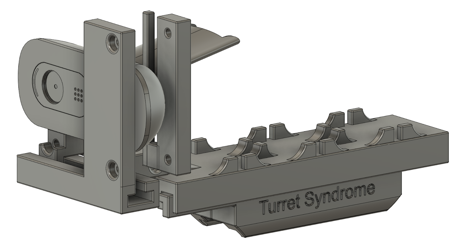
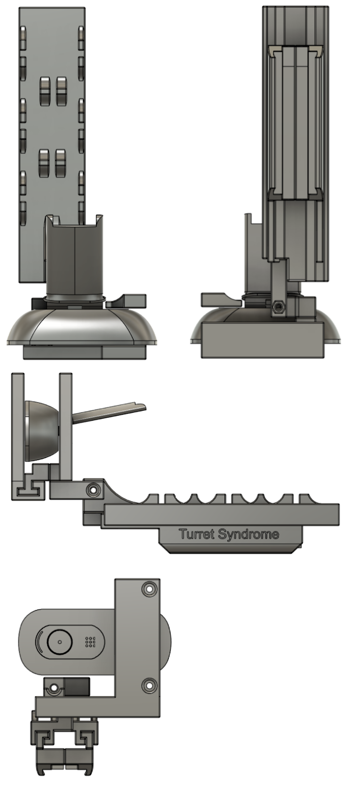
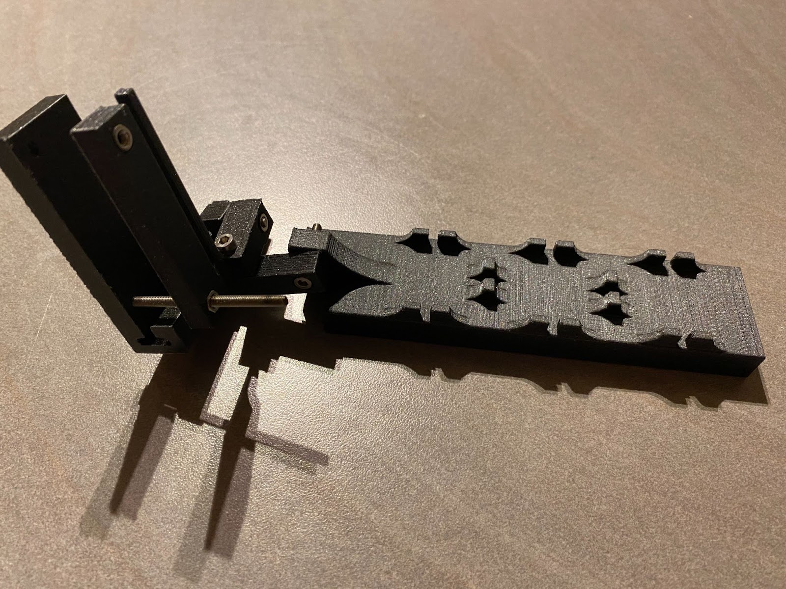
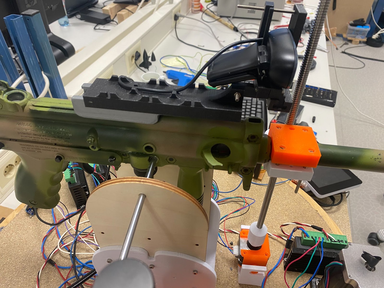
Initial CAD design – Camera Mount
I have designed a new camera mount with modularity for adjustments in mind. I have reused the old iteration of the main rail, so the new design builds on top of the old one. I will be using M3 bolts and nuts to secure and fit the camera. I have made insertions in the model to insert the head and nut as showcased in the pictures below. This is in order to remove unwanted movement and to make sure that the bolt is properly fastened. In addition, the camera module can also be rotated and adjusted in every direction. It also has the possibility to slide on the x-axis with the designed rail, to center the gun to the camera frame. Furthermore, I have made the cable management for the camera more sturdy so it does not break. This was a problem with the last iteration.
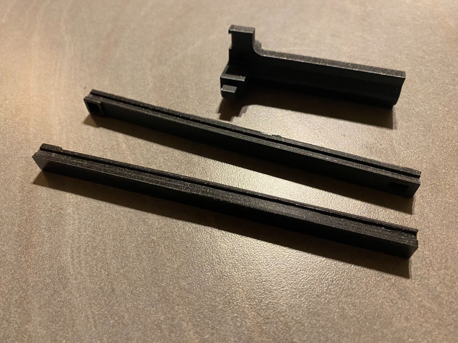
3D-printing process
For the camera I chose to print this at 20% infill and 0.15mm layer height with PLA.
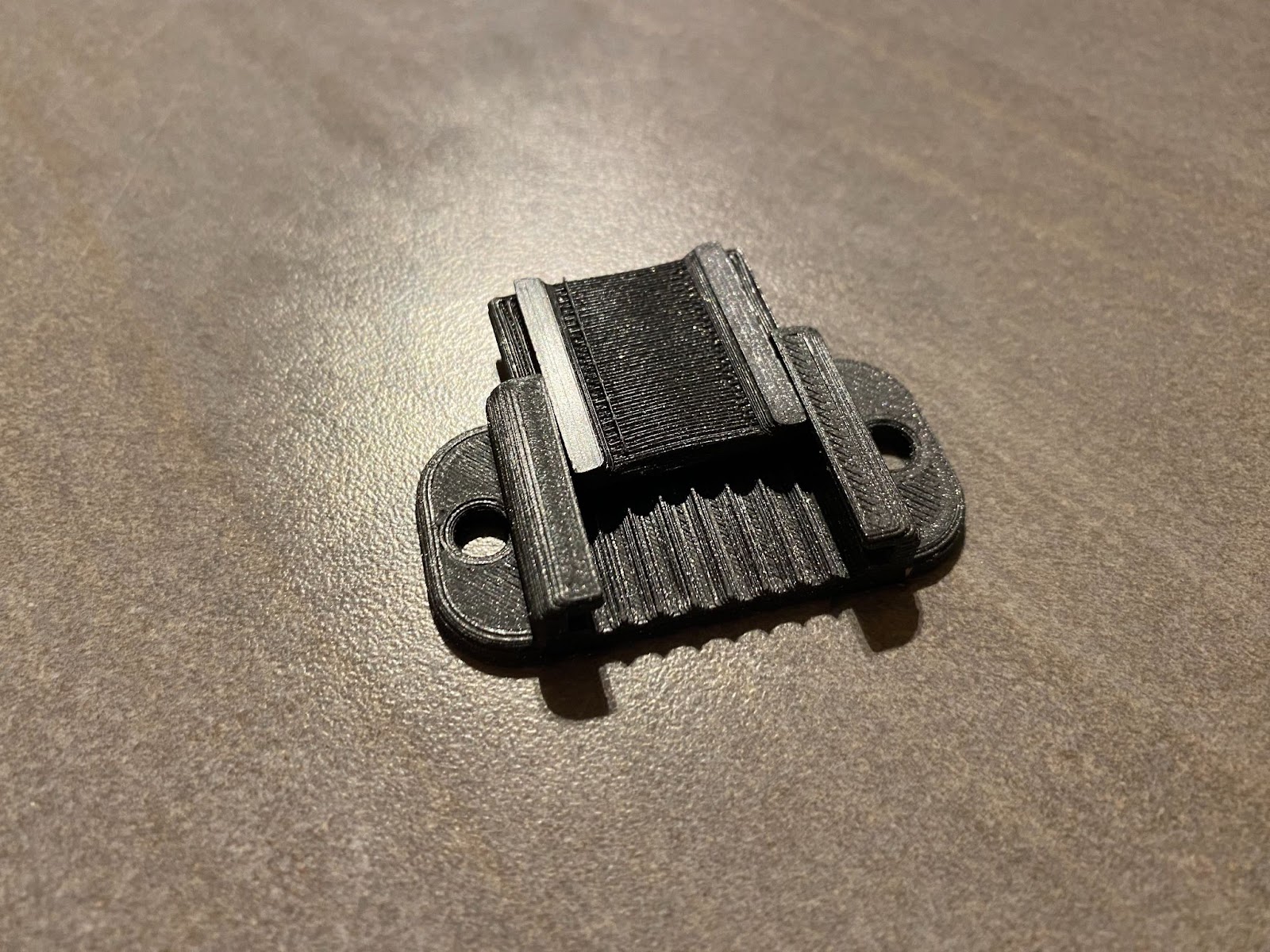
The cable holder was printed with 20% infill and 0.1mm layer height. The sliding functionality worked as intended, which I was quite happy with.
I also needed to print some new spare parts for the trigger mechanism. This is because while I was testing, I managed to break the main bolt when using the mechanism fully. The force produced by the rubber bands is quite a lot, and strains the plastic due to impact.
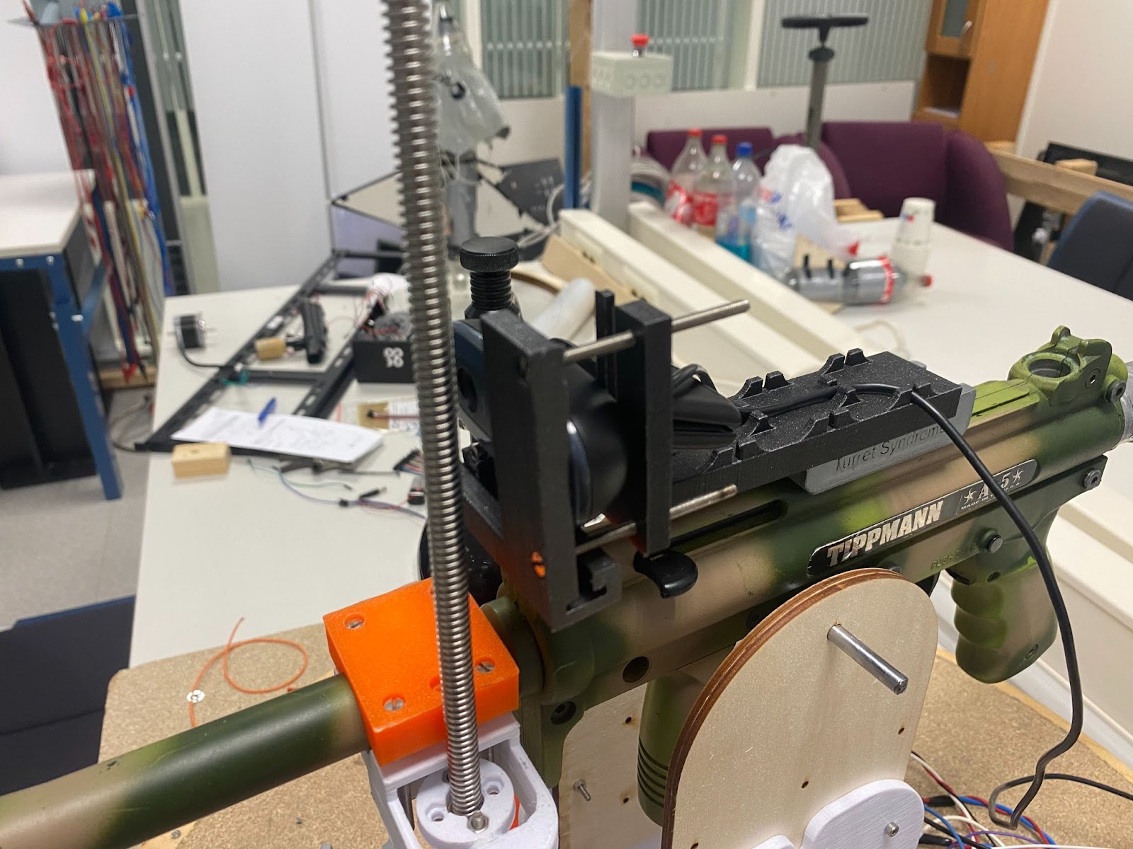
Further testing
Here is the camera mount fully assembled on the turret.
I also printed seven of the cable holders to be placed around the turret’s base. I used my day on Monday to secure most of the cables so they are not loose. I have also mounted the brackets that mats made for the battery.
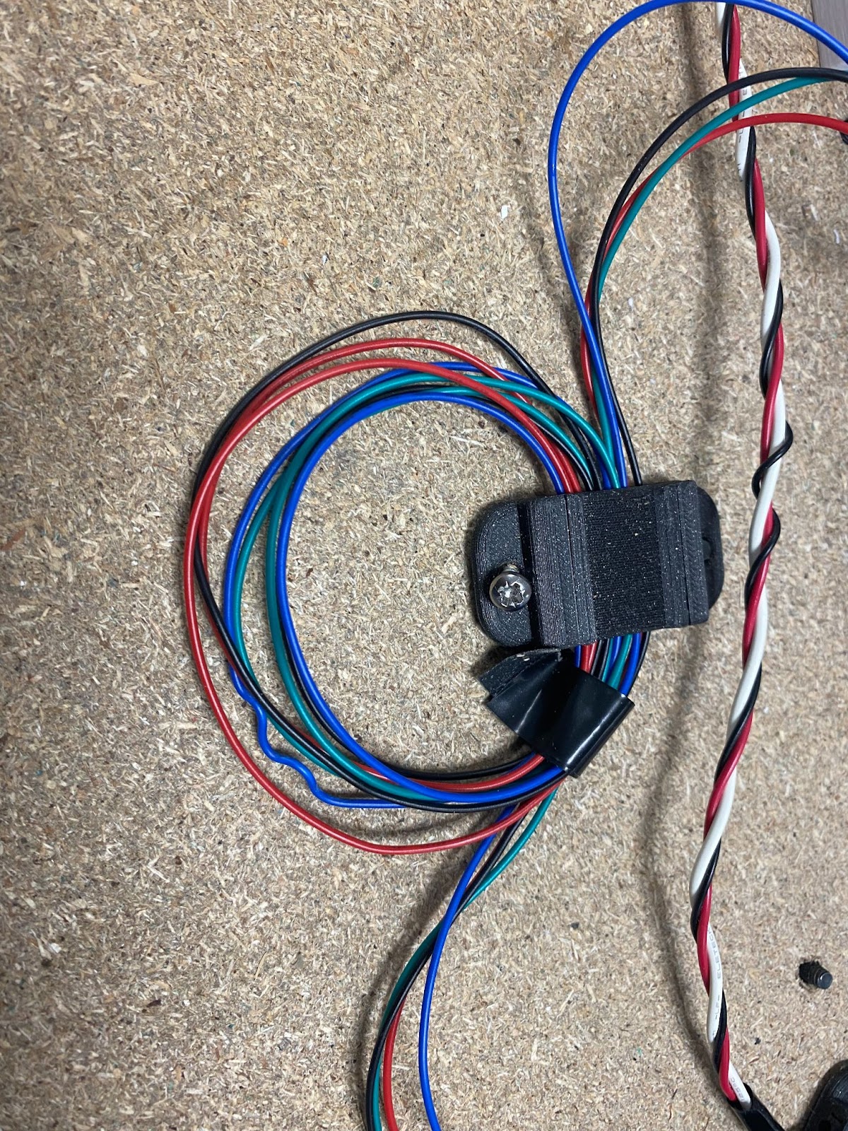
Here is the cable holder in work
Used the rest of Monday to test the entire system’s functionality with the whole group.
Next week
My plans for next week is to prepare further for the presentation.
Ole Eirik S.Seljordslia
This last week has been used on testing the system as a whole. On monday, we set up the system in Dronesona and ran some tests. We used manual control to aim initially, when we shot; we could see how much our projectile was off. Our projectile was off because our camera is mounted above the barrel of the gun. We anticipated this and had a solution ready by offsetting the camera. We offsetted the camera by moving the center point in the camera feed. This made our projectile hit exactly where we aimed.
The rest of the week was used on interfacing the trigger mechanism from the motor driver mcu as well as documenting our code contributions. The motor driver mcu sends a high voltage to the trigger mcu, the trigger mcu then responds with a high voltage on another pin that the motor driver mcu reads to confirm that the trigger mechanism has fired. Our latest reference documentation can be found in Christopher’s section.