Christopher Daffinrud
This week Ole and I spent most of Monday calculating and testing to verify how many steps our stepper motors needed for the turret to both rotate and elevate to aim at the target detected by the detection model.
Azimuth and pitch movement
Based on the horizontal FOV of our camera, 44 degrees, we calculated the following function needed for number of steps based on the distance value in pixels between the object and the camera-center:
azimuth_steps = (abs(pixel_distance) / field of view) / (stepsize / microsteps) * ⅛
On the pitch side we did a different approach based on our resolution for our camera: Our camera captures frames in a 640×480 resolution. Which means that the distance between the camera center and the top of the frame is 240 pixels:

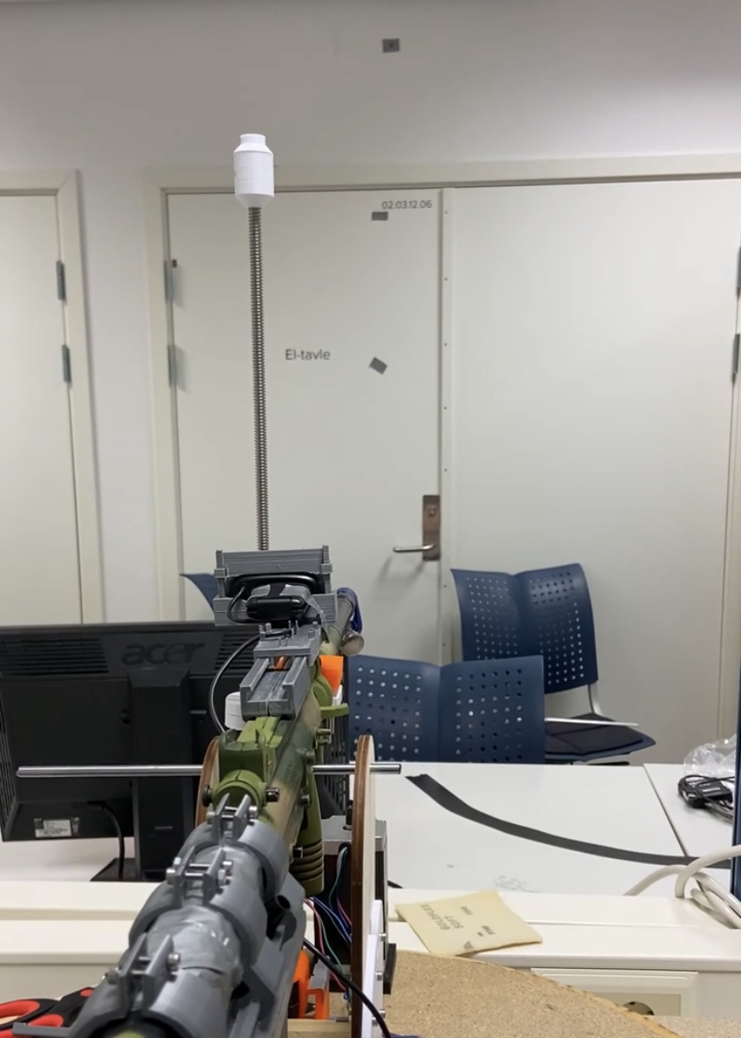
We tested to see how many steps were needed to move the turret pitch covering the distance of 240 pixels, visually confirming it by seeing that the center of our frame was right on the piece of tape.
After severe testing we confirmed that our Turret needed 7300 steps to cover 240 pixels, which gave us a factor of 30 to multiply our pixel distance in y for the number of steps needed.
Here’s a video of us testing the automatic aiming in both pitch and elevation based on the detection of a balloon object (The safety is on, without gas connected to weapon and the trigger mechanism disabled: Both electrically and in hardware for safety)
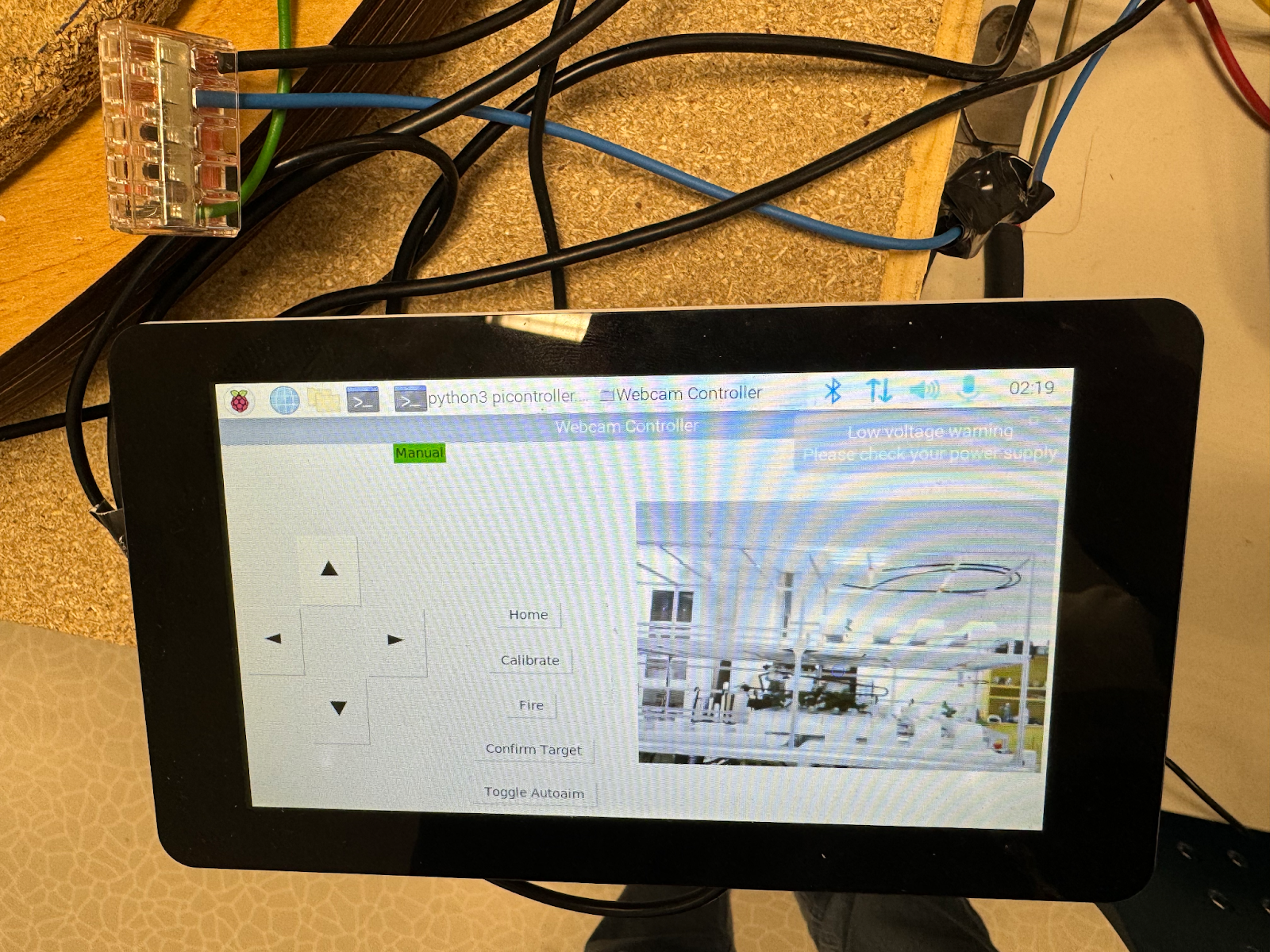
GUI implementation
I also worked on implementing the needed functionality for our GUI, connected our buttons to actual functionality for our mechanical movement and safety mechanisms. We had pseudo-functionality of the following buttons:
- Arrow-buttons: Manually moving the turret
- Toggle Automatic Aiming: For toggling automatic aiming on and off
- Confirm Target: A confirmation button needed for confirming that the turret is on target
- Fire: Fire button which triggers the trigger mechanism on the weapon firing a projectile.
The arrows for movement and the “Toggle Autoaim”-button was easy to implement as it was only necessary to set the needed variables and do some simple if-tests
The logic behind the confirmation button and especially the fire button needed some more logic for making sure to safely fire the weapon with the needed confirmation:
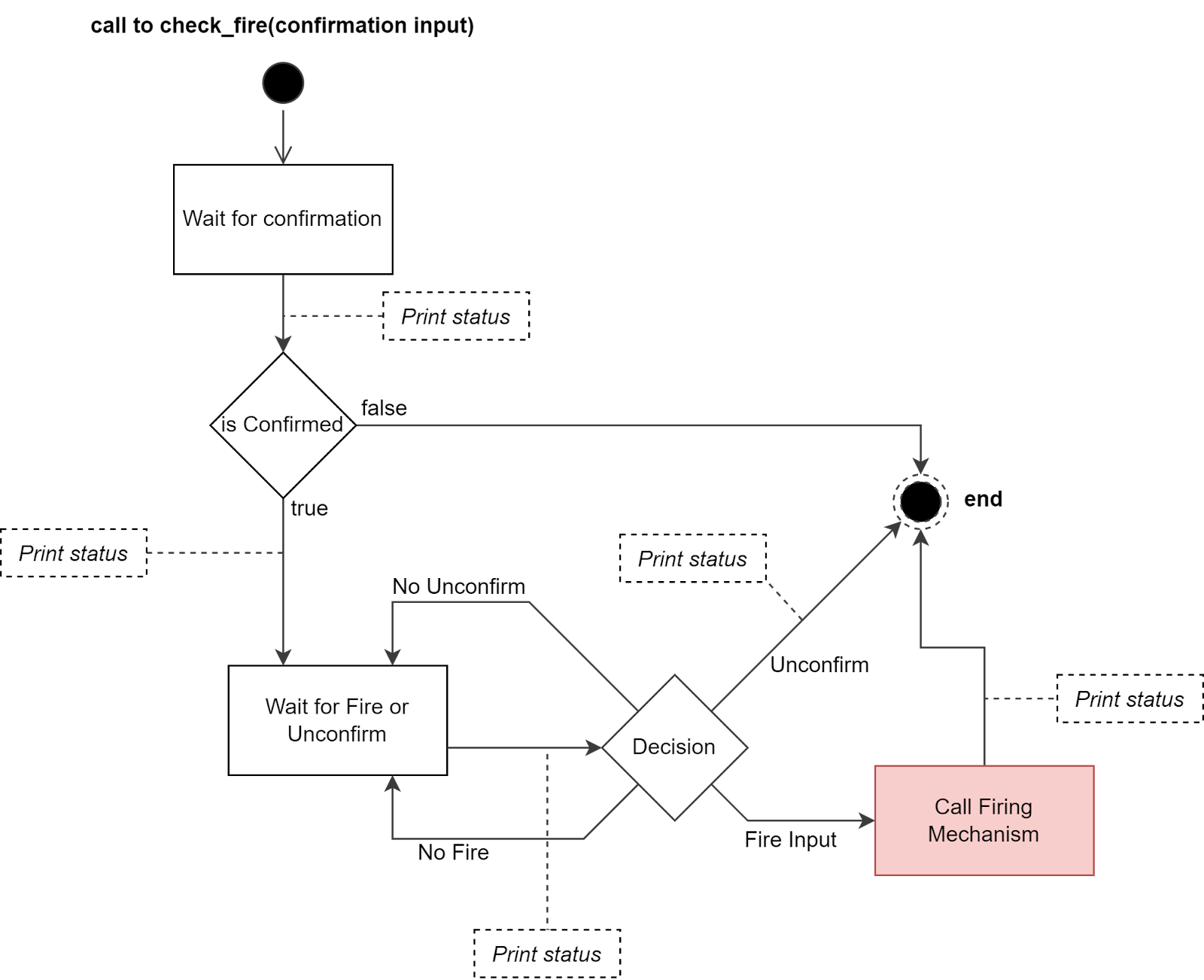
The activity diagram above explains the logic behind the firing mechanism of our Turret with the necessary “Target Confirmation” before being able to fire. It also provided the functionality of Unconfirmed a Target after Confirmation if needed, or if Confirmation has been done by user error. It also provided console output for the different stages.
For next week, and the final one we will use our week to test the system as a whole and trying to find any errors in edge cases. We also need to install our battery for our system to be operable without power from the wall.
Mats Bergum
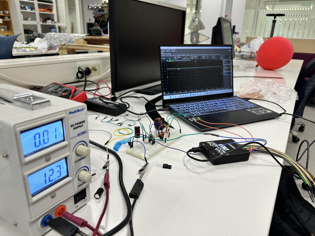
The component finally arrived this week, and I could realize the circuit on a prototype board. First, I had to confirm that the designed circuit worked properly before soldering using a breadboard.
After verifying the design, I started soldering the board meant to be used on the MVP. You can see the finished board in the image below.
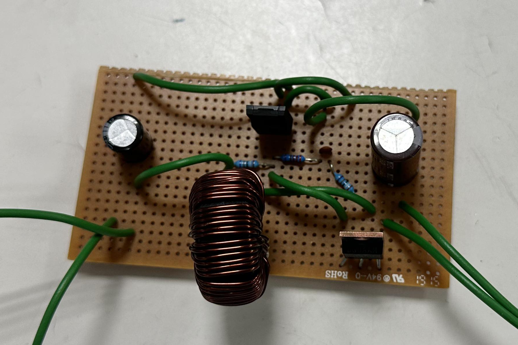
This was also tested to ensure that it was put correctly into getter. Luckily, everything seemed to work according to the simulations and measurements on the breadboard.
The rest of the week was used to design a box for the regulator. I did not finish the box because of insecurity about what connecter was available. However, it is quick to add the necessary. Holes for the connectors in the 3D design and start printing.
Hannes Weigel
This week was heavily divided between Intelligent Real Time Systems and the rocket project USN Horizon.
Despite these projects taking up the majority of my time, the Turret Syndrome system was tested throughout the week to prepare it for the upcoming demonstration.
Here the range and accuracy of the new projectile is tested. Great success!
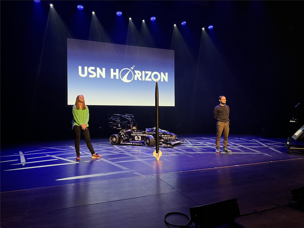
Simone and I held a talk on engineering and problem solving during the Technology Days.
To increase the lateral stability of the pitch system, I designed a new motor mount. During testing we discovered that the system had a certain amount of sway when coming to a halt. This issues was mainly fixed by the newly designed motor mount.
Harald Berzinis
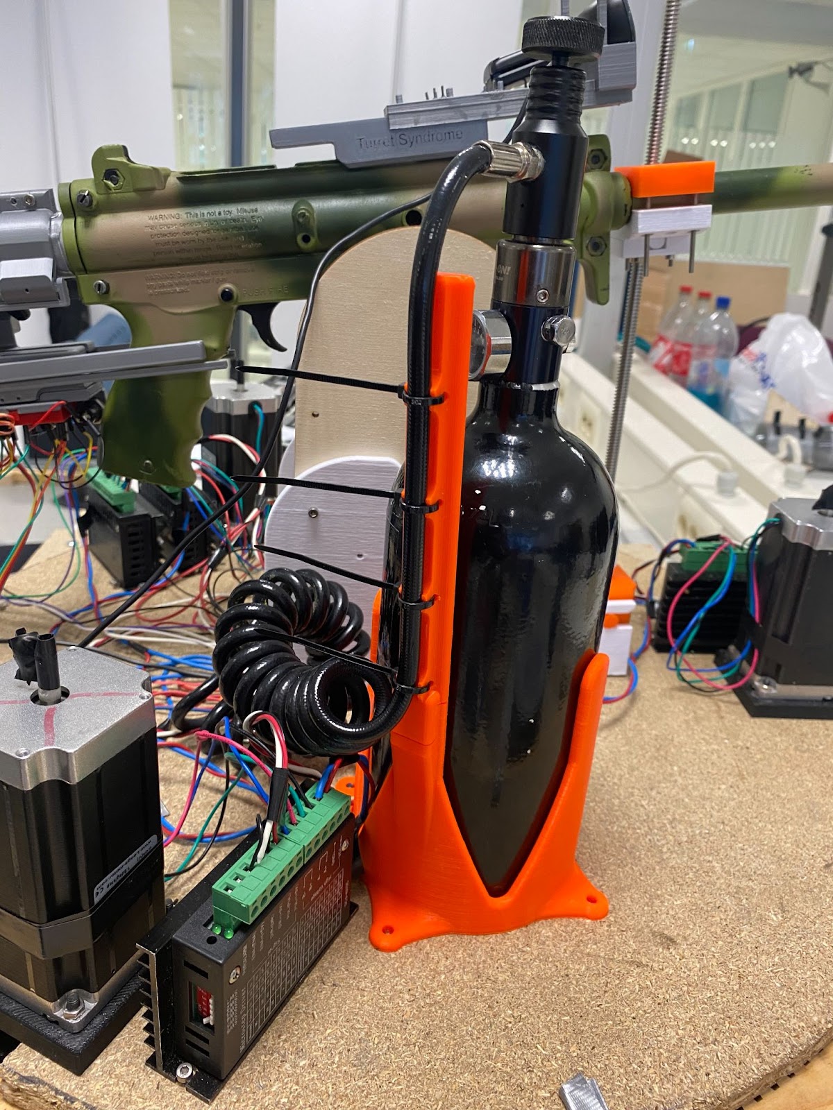
Problems, problems and problems! This week I started with 3D printing the holder for the CO2 tank. I printed the design with 15% infill and 0.15mm layer height using prusament PETG. This resulted in an unexpected result, where the print came out as expected but it was “glued” to the build plate. When taking the print off the build plate, the smooth PEI surface coating came off with it. The consequence of this was that it made my build plate completely useless. After looking further into it, it seems that the PETG filament had been exposed to moisture which resulted in it sticking to the surface, and gaining some extreme adhesion properties as I did not coat my build plate with anything else. I needed to order a new build plate from Prusa which took 1 week to be delivered. Here is a picture of the CO2 tank holder with complete installation and zip ties holding the tube.
After I mounted the CO2 tank holder, I was troubleshooting with Ole regarding the power supply for the 5V required units, this includes the Raspberry Pi and the touch screen. When hooking up the Pi and the screen, the Pi would go into an infinite boot loop and draw a maximum of 0.5A which is quite low. This was tested with a proper laboratory power supply unit and the one Mats made which resulted in the same outcome. In the specifications it says that the Pi can be powered by a separate unit and the Pi itself can power an external 5V peripheral which in our case is the screen. The issue seems to be with the Pi that we have. The solution for this will be included in next week’s Mats blog.
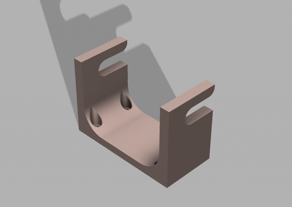
CAD-design for cable holder
After realizing that we had many loose cables that needed some tidying, I thought a good approach would be to make a cable holder. So I came up with this contraption:

The cable holder incorporates a sliding function which fastens the cables to the housing. These parts will then be placed around the turret’s wood plate and screwed to tidy up the existing cables.
Next week
The plan for the next week is to design a new camera mount that will include fasting capabilities, rotation for x,z,y and sliding possibilities. In addition, next week is also the last week for this course, so there will be a lot of tweaks and fixes for the existing system!
Ole Eirik S.Seljordslia
As Christopher mentions we spent most of the Monday calculating how we could translate differences in pixel coordinates to motor movement in both pitch and azimuth. We had an interpolation implementation ready if the movement was non-linear, but our system proved to be extremely linear. This means that we could use direct conversion between pixel distance and movement calculation.
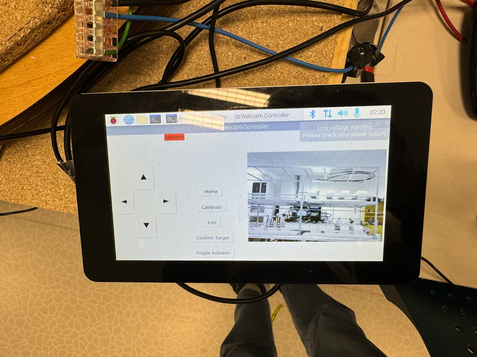
The rest of the week was spent on adding some functionality to the graphical user interface. A visual status has been added to show the user what state the turret system is in. The status is indicated with a red and green status bar. When auto aim is toggled on the system will move automatically, this is indicated with a red status bar. When the system is set to manual mode, the status label is indicated with a green label.
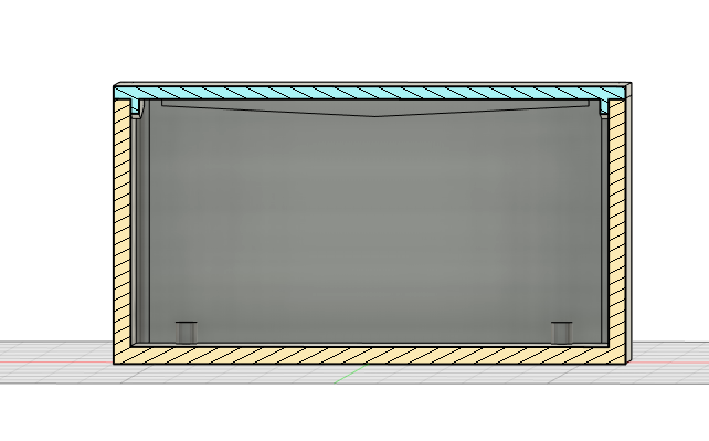
Calibration and home button was added to more quickly “zero” the position of the pitch motion. We have an issue with our system where the web camera could be squished against the pitch rod if we were to detect something very low. See picture below.
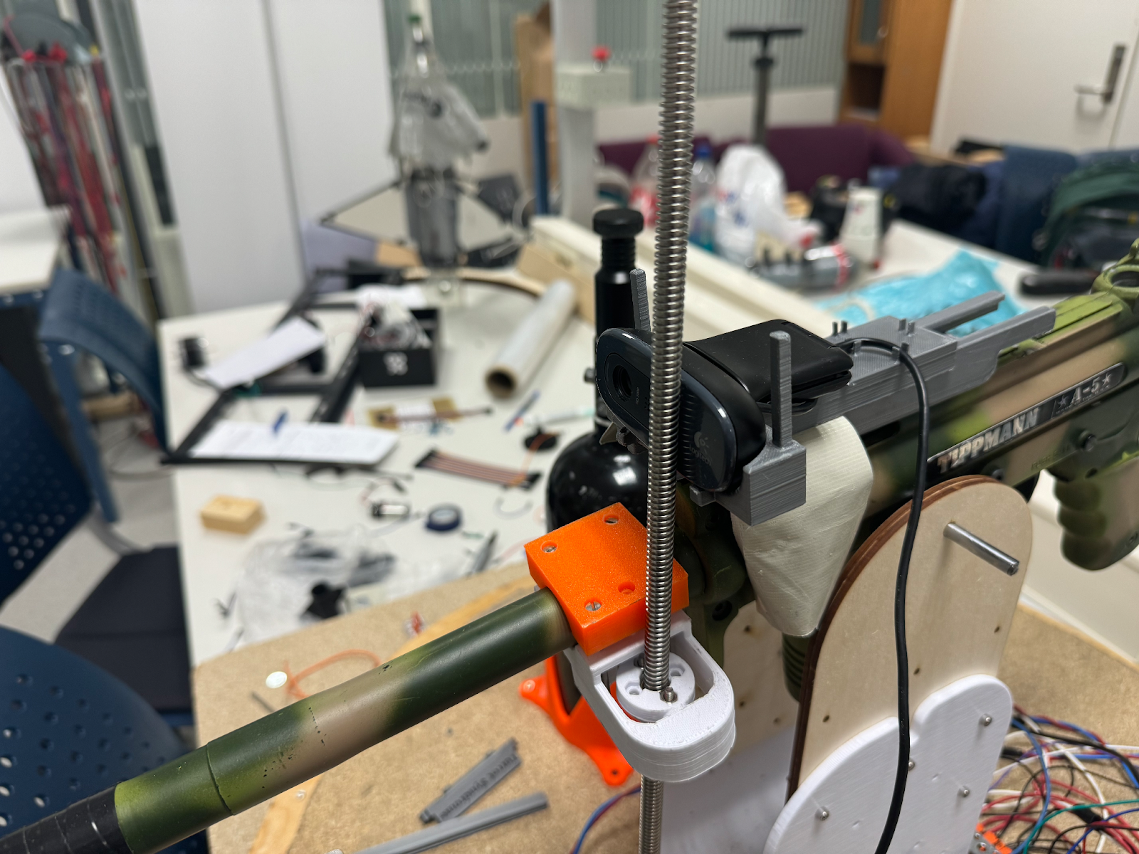
Our solution is to have absolute limits to constrain pitch movement. In order to have absolute limits, we would need a reference point. This reference point should ideally be in the middle of our detection area. If our system is restarted, we don’t know where our pitch is placed.
This is why I created a calibration button to set the reference point. By keeping a count of how many steps we have traveled, we can always home the pitch, by reversing it to end up at the calibration point. The homing function will be called when we close the graphical user interface, this way we hopefully don’t need to calibrate the system as it’s in the correct position when we boot up.