Last week we conducted the following efforts:
Discipline – Software:
Erik-Andre Hegna:
As Ask and Lars elaborated well on what we did this week, I will go into detail regarding the problem we encountered with the ultra-sonic sensors. Our initial approach and ideas regarding the ultra-sonic sensors were that it could measure distances up to 4 meters. With this we could divide the distance measured by the length of each cell and get an accurate reading of how many cells there was in one direction before encountering a wall.
Ex: Front sensing 40 cm ahead à 40 / 17.5 = 2.29 à 2 cells ahead and the position in the cell you’re in is 29/100.
The idea about this approach was that we could automatically see if we drove from one cell to another depending on the decimal value of the division (when the decimal values goes towards 0, the mouse approaches a new cell), and we could create an x amount of cells in one direction for our algorithm.
When we started testing this solution in the maze, we realized that this was not possible to do. In theory we think it was a good solution to the problem of mapping the maze, but it turned out we couldn’t trust whether the sensor was reading a wall or one of the cell dividers (black columns).
From our experiments we realized that the sensors are reliable at distances less that 20cm. At distances greater than 20 cm, we sometimes got sensor values from a black column one or two cells ahead, and sometimes we got the wall that’s further ahead. This was a very unreliable way to read. The readings seemed random, and we had to figure out a new way to map the cells.
Now we have to figure out a new way to find out which cell the mouse is in and how we sense the cells around the it.
Lars Leganger:
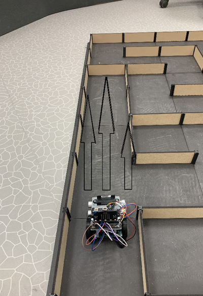
This week we started to test the values of the mouse. We measured the distance on the front sensor to see what the output is compared to real world distance. One of the problems we faced was that the front sensor does not read the entire distance ahead. The mouse usually reads all the way to the next cell from the cell it stands in but a different layout to the maze changes that. Sometimes it might read the next two cells or more. So, we decided that we are going to work with the minimum reading which is the front sensor read of the next cell it enters. We also tested the PID controller in the maze and tested the left and right sensors to see if it was able to read the edges of each cell. The video below shows the mouse running in the maze using a Pid controller while it tracks the edges. We need to calibrate it a little bit more as it didn’t pick up every cell. That is the job for next week.
Ask Lindbråten:
On Monday I spent time explaining the logical structure and thought process behind the initial implementation of the decision tree to Erik-Andre. After that we started tinkering with the micromouse, our goal was to validate that the circuitry and the sensors would function properly, so we could start playing with motor-control functionalities and values in the maze and complete the final measurement test.
Unfortunately, we encountered some unexpected results as the right ultrasonic sensor didn’t seem to be activated, despite numerous verifies and recablings of the trigger and echo pins. However, on Tuesday, some group-members talked with Steven and figured that it was actually the Microbit that was faulty, “fortunately”, and not the cabling or circuitry. So, everything was set for a productive session on Wednesday!
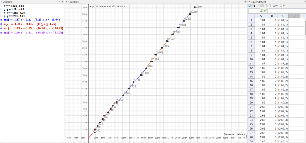
On Wednesday Erik-Andre and I met early to start the measurement test within a rectangular part of the maze with walls. Our goal was to see what values the sensors would return (configured to cm’s) when the micromouse were placed at each cm in a real-world distance of 1-10 and at every second cm from 12-50, from a wall. These values would be mapped with the corresponding real-world coordinate to create a data plot in GeoGebra, in which I could find approximate linear functions in R^2 to return y ( a real-world coordinate) based on x ( a measurement), as mentioned before.
The test took a lot of time due to constant positioning adjustments and occasional data loss when writing values to text files. However, we were largely successful up to 38 cm, under the test conditions worth mentioning. Beyond this RW-distance, the pulse would hit one of the side tiles 2-3 squares in front of the wall and bounce back, resulting in a measured distance of approximately 20 cm and rendering it completely useless for any computational and practical purposes. Erik-Andre will also elaborate further on this.
Afterwards, when we tried running motor-control functions in the rest of the maze, while activating the sensors, we actually noticed that the front sensor were mostly able to detect a wall 1 to 2 squares in front of the micromouse with decent accuracy, while any distances longer than that would render useless values. In other words, I think the interval of real-world distances we can trust the sensors to approximately measure are even smaller than the window we found under the test condition. Despite this, I still created four linear approximations for the RW-distance interval used in the measurement test, even though I think we would only use the first two. This way, we at least have more than a minimum set of functions, should we potentially need more.
- Finding the approx. function for real-world coordinate y element in [0, 10];
- Finding the approx. function for real-world coordinate y element in <10,20];
- Finding the approx. function for real-world coordinate y element in <20,30];
- Finding the approx. function for real-world coordinate y element in <30,38];
1. y(x) = 1.33806x + -0.682216;
int main()
{
    std::ifstream measures;
    std::ifstream RW_vals;

    measures.open("ALL MEASUREMENTS FILE.txt");
    RW_vals.open("ALL RW VALUES.txt");

    std::vector<double> pre_adj_dist_vals{};
    std::vector<double> RW_records{};

    double RW_value;
    int count = 0;
    while (RW_vals >> RW_value && count < 100) {
        RW_records.push_back(RW_value);
        count++;
    }

    double measure_value;
    count = 0;
    while (measures >> measure_value && count < 100) {
        pre_adj_dist_vals.push_back(measure_value);
        count++;
    }
+the least square method logic from week 8.
2. y(x) = 1.16526x + 0.203794;
int main()
{
    std::ifstream measures;
    std::ifstream RW_vals;

    measures.open("ALL MEASUREMENTS FILE.txt");
    RW_vals.open("ALL RW VALUES.txt");

    std::vector<double> pre_adj_dist_vals{};
    std::vector<double> RW_records{};

    double RW_value;
    while (RW_vals >> RW_value) {
        if (RW_value > 10 && RW_value <= 20) {
            RW_records.push_back(RW_value);
        }
    }

    double measure_value;
    while (measures >> measure_value) {
        if (measure_value >= 10.17 && measure_value <= 16.94) {
            pre_adj_dist_vals.push_back(measure_value);
        }
    }
+the least square method logic from week 8.
3. y(x) = 1.25449x + -1.05304;
int main()
{
    std::ifstream measures;
    std::ifstream RW_vals;

    measures.open("ALL MEASUREMENTS FILE.txt");
    RW_vals.open("ALL RW VALUES.txt");

    std::vector<double> pre_adj_dist_vals{};
    std::vector<double> RW_records{};

    double RW_value;
    while (RW_vals >> RW_value) {
        if (RW_value > 20 && RW_value <= 30) {
            RW_records.push_back(RW_value);
        }
    }

    double measure_value;
    while (measures >> measure_value) {
        if (measure_value >= 18.25 && measure_value <= 24.95) {
            pre_adj_dist_vals.push_back(measure_value);
        }
    }
+the least square method logic from week 8.
4. y(x) = 1.26056x + -1.40949;
int main()
{
    std::ifstream measures;
    std::ifstream RW_vals;

    measures.open("ALL MEASUREMENTS FILE.txt");
    RW_vals.open("ALL RW VALUES.txt");

    std::vector<double> pre_adj_dist_vals{};
    std::vector<double> RW_records{};

    double RW_value;
    while (RW_vals >> RW_value) {
        if (RW_value > 30 && RW_value <= 38) {
            RW_records.push_back(RW_value);
        }
    }

    double measure_value;
    while (measures >> measure_value) {
        if (measure_value >= 26.31) {
            pre_adj_dist_vals.push_back(measure_value);
        }
    }
+the least square method logic from week 8.
Visualized in GeoGebra:
Potential improvements to the adjustment functionality:
Even though the functions are continuously setup I think there is still some potential improvements to be made to increase accuracy:
- Ignore measurements under 1.5, return RW-value = 0;
- For x values corresponding to y values in <10,12>, <20,22>,<30,32>, we can find a more accurate y value, in for instance the first interval: <10,12>, by calculate two y values for x = 9 using the first and second function, adding the results and dividing by two to find an average corresponding y between those two approximation functions.
Potential objectives for next week:
- Test these adjustment functions.
- Adjust and develop the decision tree implementation to account for a potential new way of registering nodes/cells/squares (Erik Andre discusses this).
- Check if the micromouse is able to map a maze path into a graph, that can be used to make physical motor-control actions.
Discipline – Electrical:
Hugo Valery Mathis Masson-Benoit:
Nothing to report this week.
Jemima Niquen Tapia:
This week we had some problems with the final design and the PCB connections. We checked the sensor’s connections as we had one that was working well but not the others. After some research we couldn’t find the solution, so we went to ask Steven. It looks like the micro bit was broken, a pin wasn’t working well, so we changed that.
After this we have been able to weld the wires to the motor board and change some wires to prevent any problem because of them.
The plan for next week is to do a schematic that way in case there is any problem see easily where the problem can be. Also prepare the presentation for the oral exam.
Discipline – Mechanical:
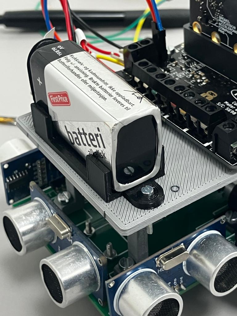
Cesia Niquen Tapia:
This week for finishing with some of the needs for the micromouse I’ve designed and assembled the supporter of the battery. So now we have an easy access to it. Here it could end the mechanical work, unless we end up needing the magnets, which then only the wheels should be changed. For this , it would only take printing the designs that were already made for this.