Andreas
This week has been spent tinkering with the filer function we made so that we could change the filter type, coefficients and order without having to change any code other than some variables. This makes tinkering with the filter to find the one that suits us best is very easy to achieve.
On Friday, we received some components we will exchange next week. This will most likely be what I spend the next couple of weeks on, as well as helping Bendik create the motor controller and implement the rotary encoders. Luckily the encoder circuit is quite easy to assemble and even though we will be changing the power source to 9V, most of the components I will need to change are a couple of resistors.
Bendik
This week I have been working with implementing a PID-controller for the micromouse. This is to get the mouse to be able to drive in a straight line between 2 walls. To accomplish this, the 2 motors must be given variable PWM signals, so that the RPM speeds can align resulting in the mouse driving straight.
To calculate the error, I simply subtracted the value from the IR sensor on the right side of the mouse, with the value from the IR sensor from the left side.
Error = IRSensorLeft – IRSensorRight
I then have 3 values for the PID controller.
Kp = Proportional Gain
Ki = Integral Gain
Kd = Derivative Gain
These are constants that will define the behaviour of the PID controller, so these values need to be calibrated properly by testing.
Each of these constants are used in formulas to produce outputs, and these 3 outputs are summed to create the PID controller output.
P_output = Kp * Error
I_output = Ki * ∑past errors * deltaTime (change in time)
D_output = Kd * (deltaError/deltaTime)
PID_output = P_output + I_output + D_output
This output can now be used to regulate the PWM signals like so:
leftMotorSpeed = baseSpeed + PID_output
rightMotorSpeed = baseSpeed – PID_output
Now I need to test this on the micromouse itself.
Marte
After a month of patiently waiting, my 3D printer finally arrived this week! 😁
This is a new experience for me, and I look forward to use it in the project and hopefully learn a lot about 3D printing in this process.
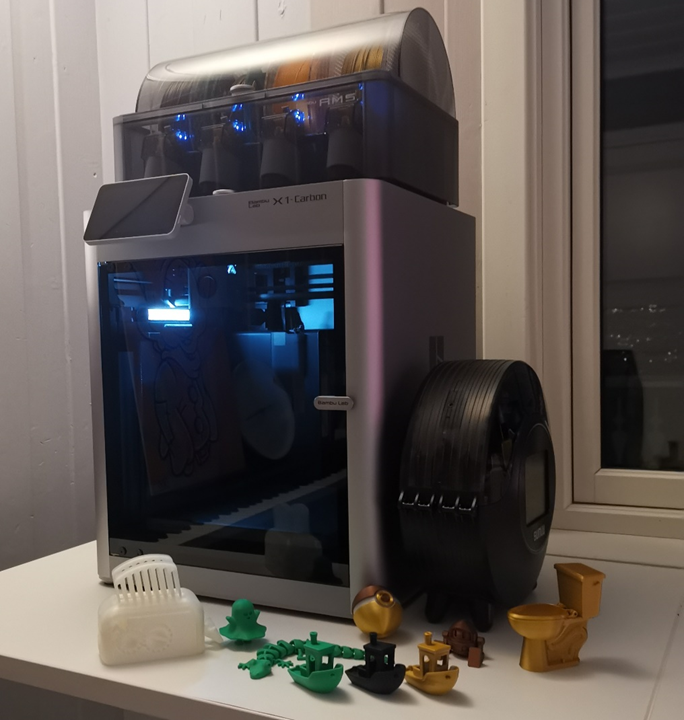
On the picture is the beautiful Bambu Lab X1 Carbon Combo, with some of the models I have printed this week. I have only printed in PLA so far, but it is possible to a lot of different polymers on this printer. I ordered a lot of different filaments, but unfortunately not all of them have arrived yet. PLA is a nice filament to use in the beginning, easy to print, cheap, but its mechanical properties are not always adequate. One special thing about this printer is that it can print polymers that are strengthened by carbonfibers. I look forward to testing this and other filaments like PA, ABS, PETG, TPU and PVA (water-soluble support material).
A timelapse of one of the benchies I have printed:
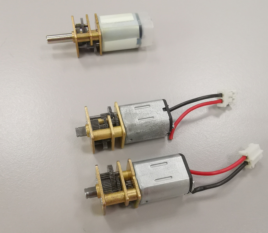
We have decided to switch to smaller motors, and I have spent some time this week on how to implement them to the micromouse with motor encoders. Unfortunately there was only one motor left with a long shaft, so we have to use the ones with only 3mm shaft. Hopefully it will be long enough to transfer the torque from the shaft to the gear I have designed.
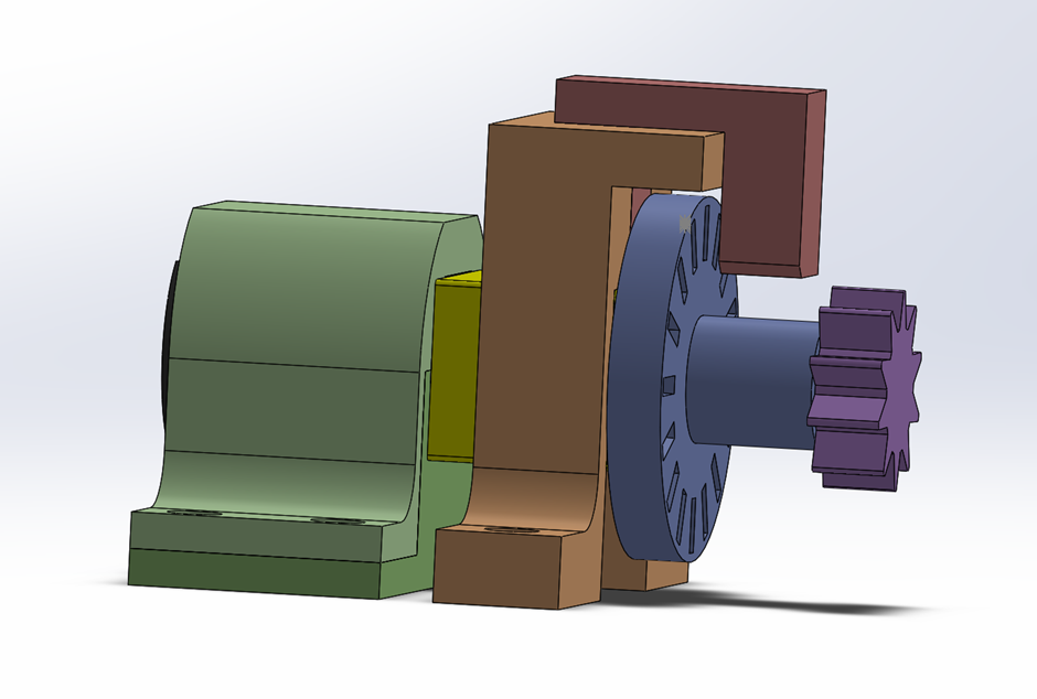
I modelled a design in SolidWorks, with housing for motors, housing for photomicrosensor, motor encoder and a gear. The idea is that the gear will be connected to two wheels with gears:
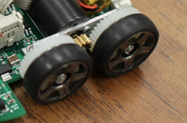
When it comes to manufacturing techniques, I will try to produce the motor encoder both by 3D printing and laser cutting, to see which will be more accurate and fitting. I will also try to 3D print motor encoder and gear in one part, to ensure torque being transferred correctly. In addition there are a lot of small parts in that subassembly, and I expect mounting them together can be challenging.
In the upcoming week I will continue with the new design, produce all the parts and assemble the hardware. It is only a couple of weeks before the project is due, and a lot of work remains to be done.
Vendel
This week we have been digging down trying to decide what to do about the car to finish it by the submission date. We have got a pretty good setup already, but as was shown in the drag race, it still doesn’t actually perform as we had hoped. The filtering has been dealt with though, thanks to Andreas and Bendik’s work over the past weeks, and I have managed to touch up the maze algorithms to the point where it should be implementable in Ada.
I have not done much work in Ada before, and I have been, perhaps purposefully, been postponing doing it, but there is nothing for it now, and I have to dive in to get this project done. Luckily, it seems that Ada is a language I will be able to wrap my head around rather quickly, and with all of the programming technically done, one project by me and one by Andreas, I should be able to translate it of sorts from C++ and Python into executable Ada code without too much trouble. It’s only a few hundred lines of code, how hard can it be? How hard can it be, she said with the full hubris of an engineer. This will either take an afternoon or the entirety of the time before the deadline, and only maybe it will work by the submission date.
Still, how hard can it be?