Christopher Daffinrud
On Monday when testing our system as a whole together with our software we encountered some issues when calling the motors for rotating the Turret. The turret rotated both clockwise and counterclockwise based on where the Detection Model detected our object, but the rotation in itself was “laggy”, giving us a feeling that the signal to the motors was not ideal. We confirmed this by analyzing the signal output from the raspberry Pi.
We think the bad signals is due to the Raspberry Pi OS not prioritizing the motor calls as needed when running those is a separate thread.
For Tuesday we wanted to address this lag by using the hardware Pulse Width Modulation (PWM) pins on our Raspberry Pi.
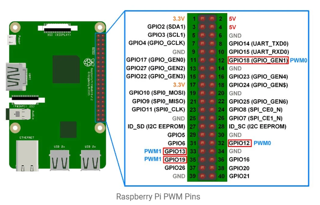
Using GPIO18 as shown in the picture, together with Mats, we created a function outputting a PWM signal instead. We calculated that by sending a signal of 1600Hz for a duration of 8 seconds should rotate the Turret 90 degrees. (Based on a step size of 1.8 degrees with a 1:8 relationship with the sun-gear where the gun is mounted).
The PWM-function resulted in fixing the “lag” issue, but it still only rotated the Turret around 85 degrees instead of 90. Ole will elaborate more on this in his post.
For next week: Continuation of troubleshooting and implementing the software to follow our desired requirements. We need to test and calculate for the pitch elevation as well as the trigger motor.
Ole Eirik S.Seljordslia
After using the monday and tuesday on testing our turret system, we had problems with running the motors precisely and smoothly. We found out that the raspberry pi did not produce great output for our motors. We first tried a blocking implementation that would use `time.sleep`. This worked when the system was not under load by other processes. But when we deployed our whole system, the thread performing the blocking bitbanging would miss on the timing due to the process not being prioritized at the right time.
Our next implementation used the raspberry pi’s PWM functionality, this would be non blocking since the timing is implemented in hardware. This solution worked well with the frequency we tried to obtain, but it would randomly skip steps. This meant that this solution would be sporadic inconsistent when we move our motors.
Since timing the PWM signal proved to be a challenge on the raspberry pi when it was under load, we decided to offload this task to a microcontroller. I used the remainder of the week on implementing and testing this solution.
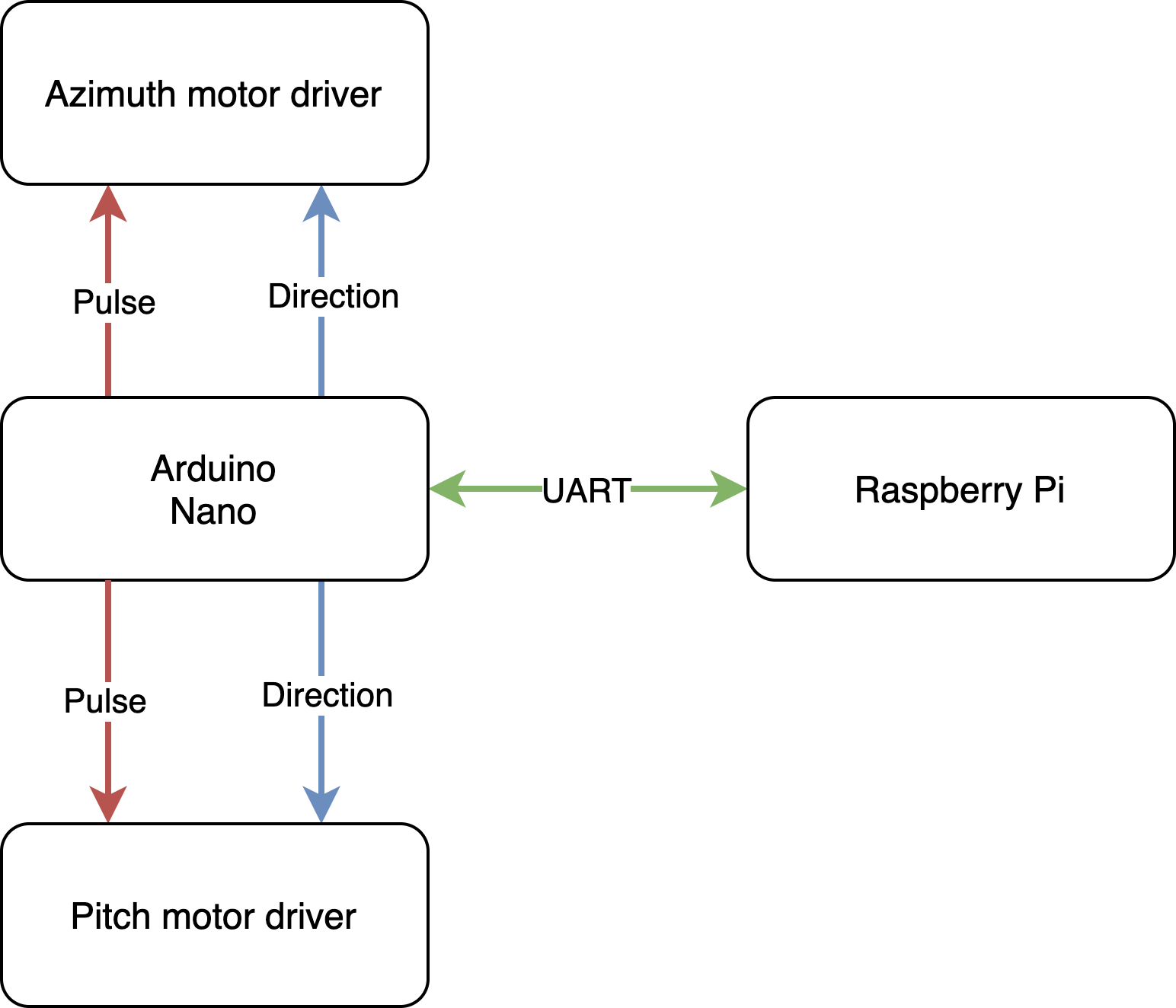
Our idea was to send commands to an Arduino Nano over UART, then the microcontroller could time the signal. Arduino Nano has 6 pins that support hardware PWM, these pins support either 490Hz or 980Hz(Arduino analogWrite). We wanted to run our motors at 1300Hz, this proved to be a good frequency combining speed and smoothness with our setup. We could have one of Arduino’s frequencies but this would limit our possibility to optimize our system later on.
One possible solution to adjust the frequency is to adjust a prescaler factor (1,8,54,256) for one of the Nano’s timer clocks. This would help to adjust the frequency of the PWM pins, but we still need to know how many pulses have we sent.(Adjusting prescalers).
I chose to bitbang the pulse signal with a timer interrupt, this way I could count the number of pulses and control the frequency with high precision.
1 2 3 4 5 6 7 8 9 10 11 12 13 14 15 16 17 18 19 20 21 22 23 24 25 26 27 28 29 30 31 32 33 34 35 36 37 38 39 40 41 42 43 44 45 46 47 48 49 50 51 52 53 54 55 56 57 58 59 60 61 62 63 64 65 66 67 68 69 70 71 72 73 74 75 76 77 78 79 80 81 82 83 84 85 86 87 88 89 90 91 92 93 94 95 96 97 98 99 100 101 102 103 104 105 106 107 108 109 | #include <Arduino.h> #include <definitions.hpp> #include <ArduinoJson.h> /** * @brief * Struct to represent motors */ struct motor { uint8_t pulse; uint8_t direction; unsigned int steps; }; volatile motor azimuth = {.pulse=TurretSyndrome::Azimuth::pulse, .direction = TurretSyndrome::Azimuth::direction, .steps = 0}; volatile motor pitch = {.pulse=TurretSyndrome::Pitch::pulse, .direction = TurretSyndrome::Pitch::direction, .steps = 0}; volatile motor* motors[] = {&azimuth, &pitch}; volatile bool done = false; /** * @brief * Start timer1, set compare with value in microseconds * @param value */ void startTimerOne(unsigned int compare) { //Approx. 4us runtime TCCR1A = 0b00000000; TCCR1B = 0b00000010; OCR1A = compare; TCNT1H = 0; TCNT1L = 0; TIMSK1 = _BV(OCIE1A); } /** * @brief Interrupt service routine * Flips pulse pin of motor if number of steps is not reached. * */ ISR(TIMER1_COMPA_vect) { startTimerOne(TurretSyndrome::ticks); // For loop takes approx. 32us for(auto& m: motors) { if(m->steps != 0) { digitalWrite(m->pulse, !digitalRead(m->pulse)); if(!digitalRead(m->pulse))--m->steps; } } } /** * @brief Message from raspberry pi * Assign steps and direction to correct motor. */ void handleIncomingMessage() { StaticJsonDocument<100> document; if(deserializeJson(document, Serial) != DeserializationError::Ok) return; if(document["A"]) { azimuth.steps = document["A"]["S"]; azimuth.direction = document["A"]["D"]; } if(document["P"]) { pitch.steps = document["P"]["S"]; pitch.direction = document["P"]["D"]; } done = false; } /** * @brief Confirm that motors have performed steps. * */ void sendResponse() { Serial.println("Done"); done = true; } void setup() { Serial.begin(115200); for (auto& m: motors) { pinMode(m->direction, OUTPUT); pinMode(m->pulse, OUTPUT); m->steps = 100; } // unsigned long m = micros(); // startTimerOne(TurretSyndrome::ticks); // Serial.println(micros() - m); } void loop() { if(!azimuth.steps && !pitch.steps) { if(Serial.available()) handleIncomingMessage(); else if(!done)sendResponse(); } } |
The interrupt service routine will toggle each motor’s pin and reduce the number of steps by one if it’s a falling edge. The ISR uses `digitalWrite` and `digitalRead` which are quite “slow” functions if we compare them to writing directly to registers. But this is a nice abstraction with a cost that we can accept.
The critical function of this code is `startTimerOne`, this function sets up timer one on the Atmega328P to trigger after a number of systemticks. The function starts by configuring `TCCR1A` to 0 which means normal port operation and compare output to disconnected. It then sets `TCCR1B` to 2 which results in setting a prescaler of 8.This means that Timer1 only increments after 8 system ticks. Setting TCNT1H and TCT1L to zero will make the timer start at zero. `TIMESK1 = _BV(OCIE1A)` will configure an interrupt mask for the timer, and set up comparison of `OCIE1A` with Timer1. Reference: Atmega328P datasheet, see page 108
This means that we can calculate the number of ticks we need with the following formula:
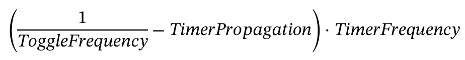
Where `ToggleFrequency` is 2 times the desired frequency(Each time we toggle the pin). `TimerPropagation` is the time it takes the Arduino Nano to run `startTimerOne`, which is approximately 4 microseconds(This was measured with a test code). And TimerFrequency being the system clock divided by the prescaler, in this case (16/8 = 2)MHz. We don’t need take into account the time it takes to run through each motor and check if it needs a pulse, because this will be shifted by the same time each toggle. Some variance can occur but this is jitter we cannot estimate.
This yields:
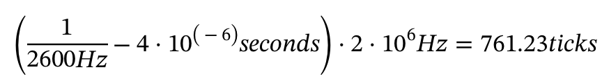
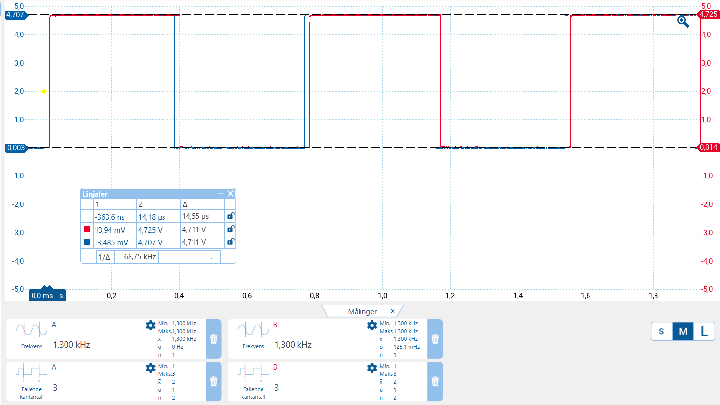
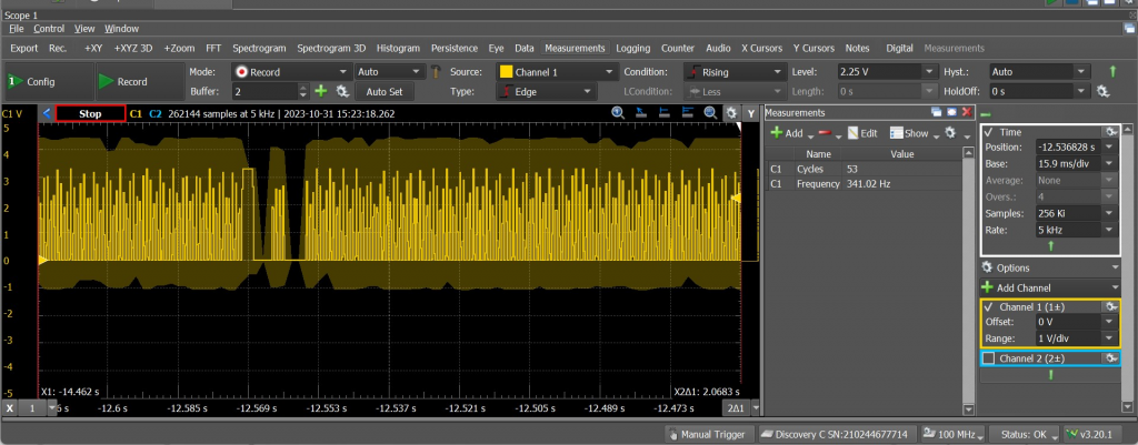
This could be verified by measuring each motor pulse pin. This first image is a test of 100 steps with a frequency of 1300Hz. Azimuth pulse is on channel A while Pitch pulse is on channel B.
This next measurement is to look at the time between azimuth and pitch. Here we can see that there is about 14 microseconds between the azimuth motor and pitch motor; this could be optimized with using registers directly, but it does not matter for us that pitch and azimuth move unsynchronized since they move independently.
Harald Berzinis
This week I have been busy with 3D-printing the camera mount, and initial testing of it. I have later made a design for the CO2 tank holder.
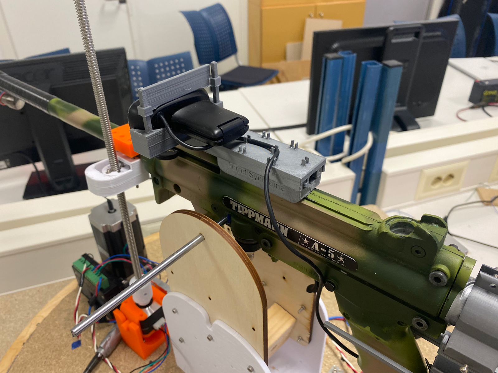
Camera Mount
The camera mount was printed with 20% infill at 0.15mm layer height. The main rail and the camera mount fit quite well together, but I needed to sand down a little for a smooth glide. Below are some pictures showcasing the camera mount’s modularity. Cable management extrusions are also working well.

CAD-Design for the CO2 Tank Holder
After I was done testing the rail, I started designing the CO2 tank holder.
The holder will be mounted with four screws to secure it to the wood plate. In addition it will consist of two parts, one being the main body, and second being the extension rail. This is because the size of the model will exceed my maximum build plate height. The extension rail will be used to route the tube of the CO2 tank and securely mounted with zip ties. Below are some screenshots showing how the tank holder will look when it is completed.
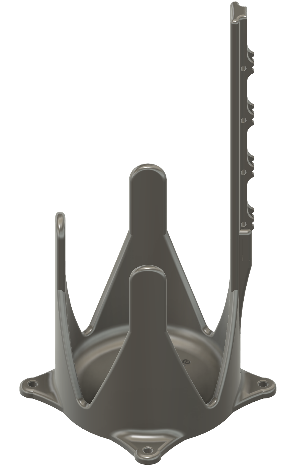
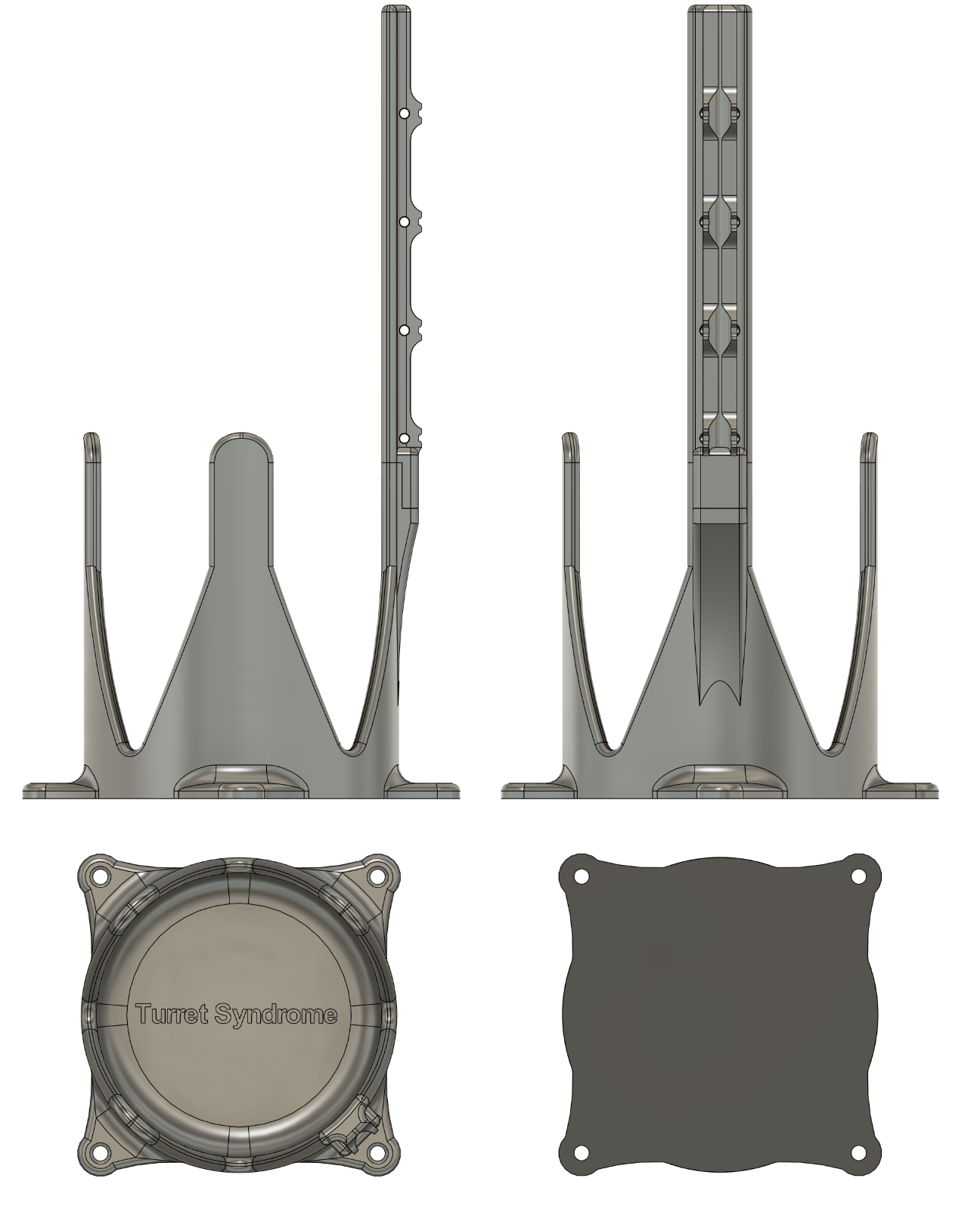
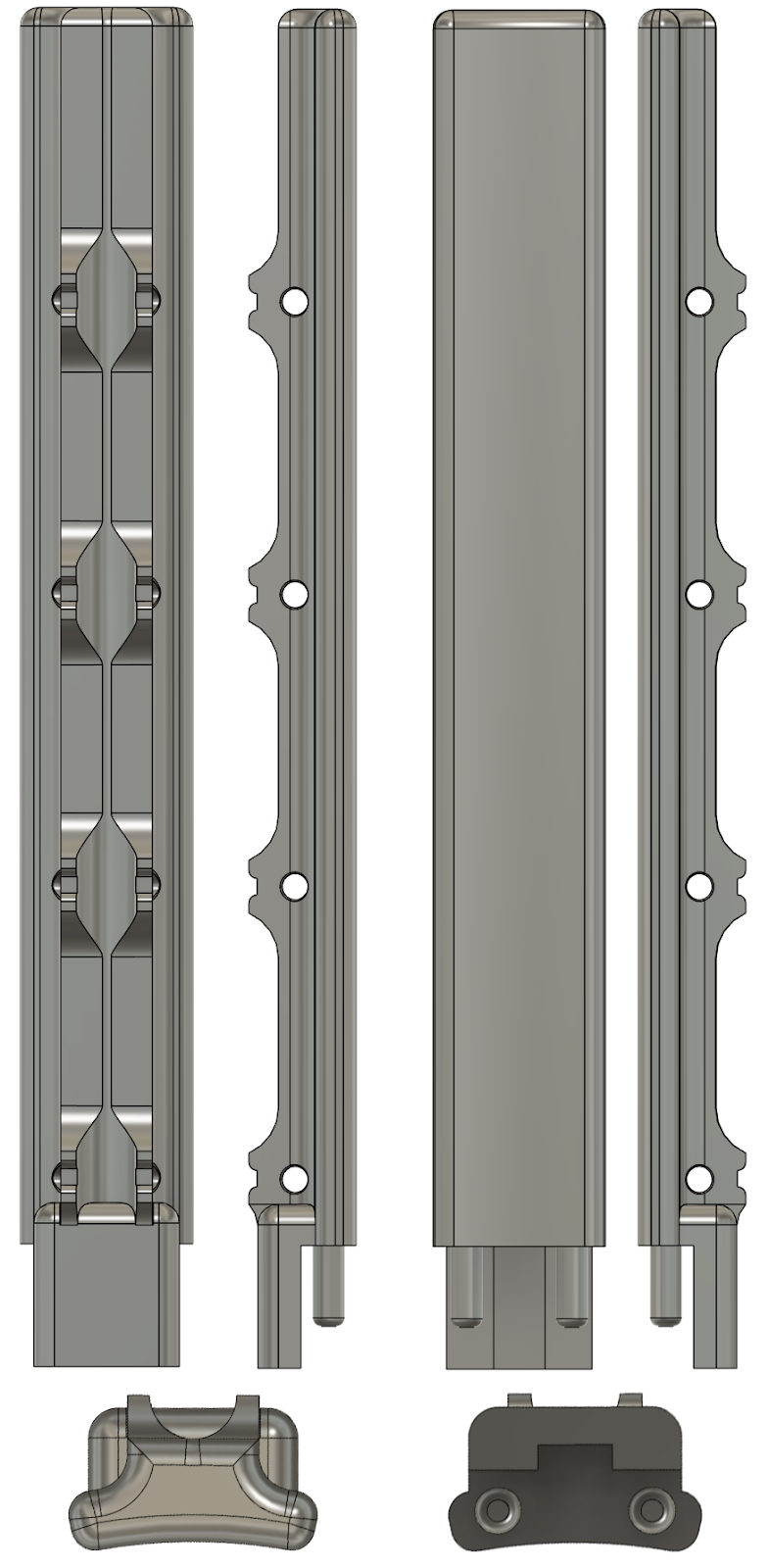
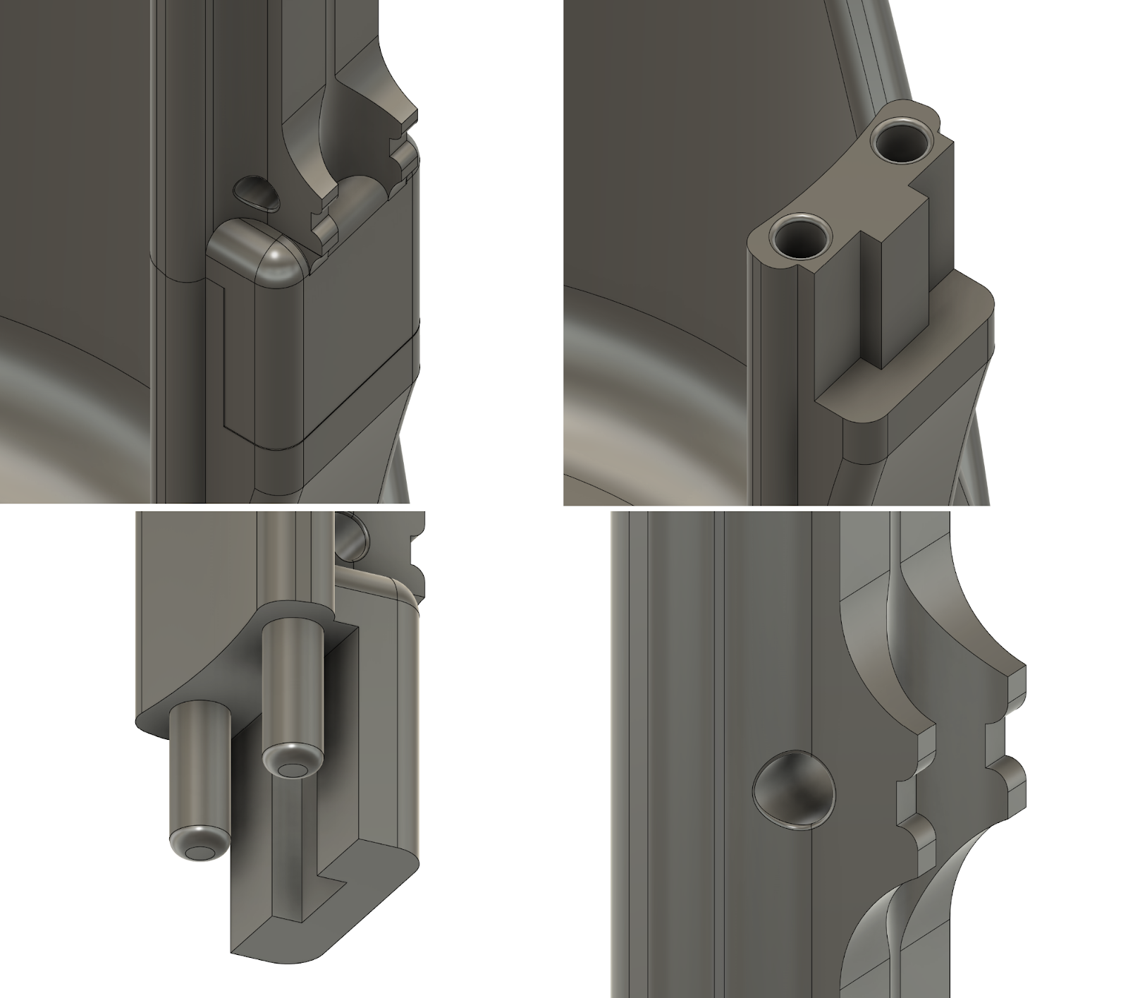
Above are three pictures that show how the tank and the extended rail are mounted together. The forth one shows how the zip ties will be holding the CO2-tube in place.
Next week:
Next week I will be printing the entire holder, and testing it further.
Mats Bergum
Still have not received all the necessary parts for the 5-volt regulator, still waiting on the 50 μH inductor. So no progress there. However, Steven got confirmation that the part was on its way.
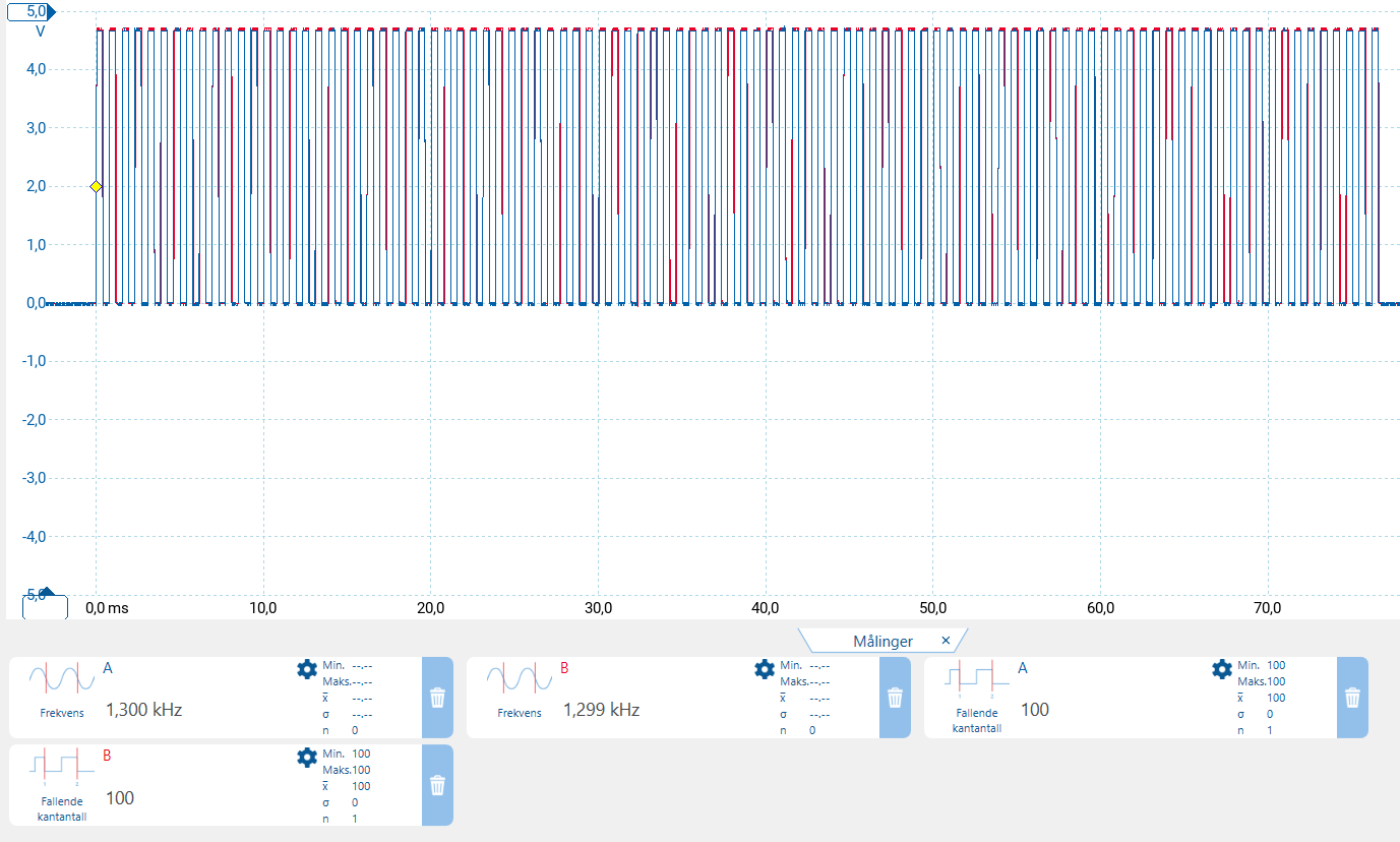
On the other hand, testing on the pulse signal for the motor controllers was conducted. This was done with Christopher and Ole. We strongly suspected that the “laggy” movement was connected to the pulse signal. As you can see in the picture below we were correct.
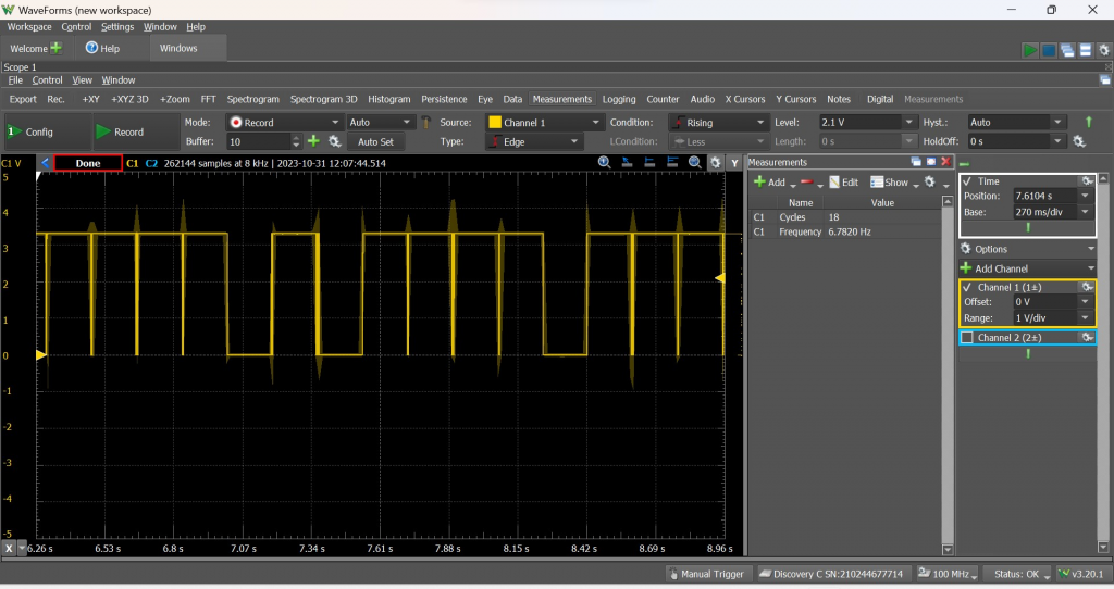
This indicated that the Raspberry Pi could not properly manage the timing with all the other processes. So, we tried to use an integrated PWM port on the Raspberry Pi. This gave us a better signal but was not nearly good enough to use for controlling.
Measurement of pulse signal using PWM pin.
From the results, we came to the conclusion that it was necessary to allocate this task to an Arduino nano, to properly send the correct signal.
Hannes Weigel
Projectile 2.0
Some real-life testing of the previously designed projectile revealed some issues.
The first design would slide on the outside of an extended barrel. This proved to be a subpar design, as the acceleration of the projectile was far too short, resulting in a meek 5 meter lob shot.
Without increasing the length of the projectile by a substantial amount, this approach would not suffice.
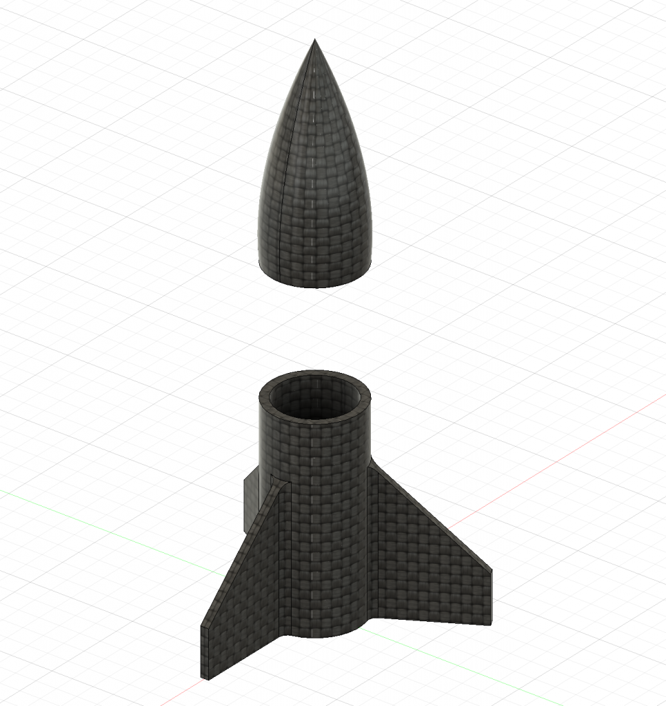
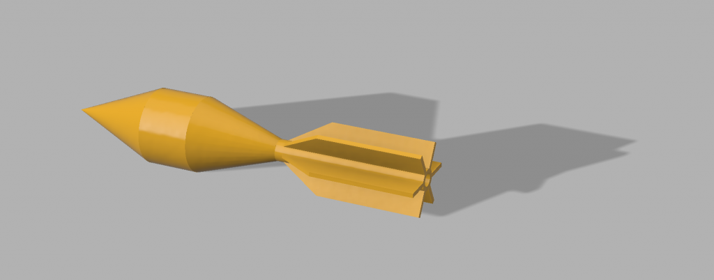
I redesigned the projectile to instead be shot from inside the barrel. This projectile features a mortar-like shape, with 6 aft fins. The projectile consists of 4 separate pieces; The nosecone, the body tube, the aft transition, and the fin tube.
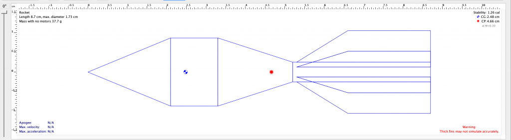
These 4 parts were 3D printed with varying infill and # of perimeters, with a weight bias towards the front. The simulated stability of the projectile is 1.26 which is remarkably stable.
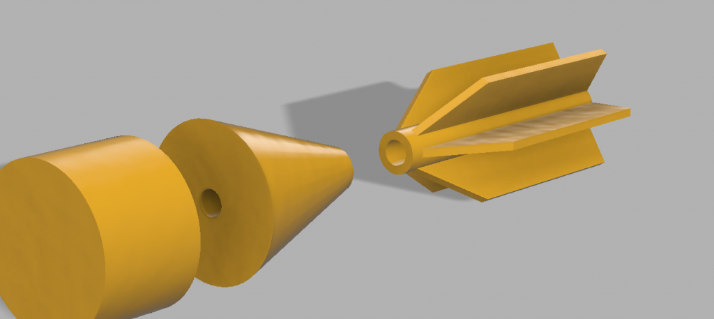
The aft transition and fin tube feature a 2.8 mm hole. As the parts were glued together, there was a chance that the seam between the aft transition and fin tube would be too fragile. Therefore said 2.8mm hole could accomodate a small M3 bolt with the head cut off.
As the seam indeed proved to be weak, the aft transition and fin tube were held together by a small cut M3 bolt.
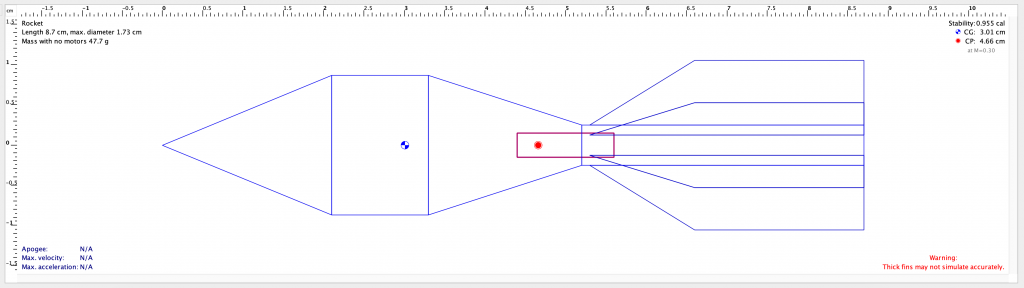
With the bolt added, the center of gravity (CG in checkered blue and white) shifted backwards and worsened the stability by 24%
Despite a stability margin of less than 1, the projectile flew incredibly straight and stable in +20 meter tests.