Ole Eirik S.Seljordslia
We started this week off on Monday by testing our implementation from last week. Our threading solution looked to work good on paper but we need to validate this by testing the implementation. I think we experienced all the typical multiprocessing problems; deadlock, race condition and starvation. But we tackled each problem one by one, and by the end of the day we had working code.
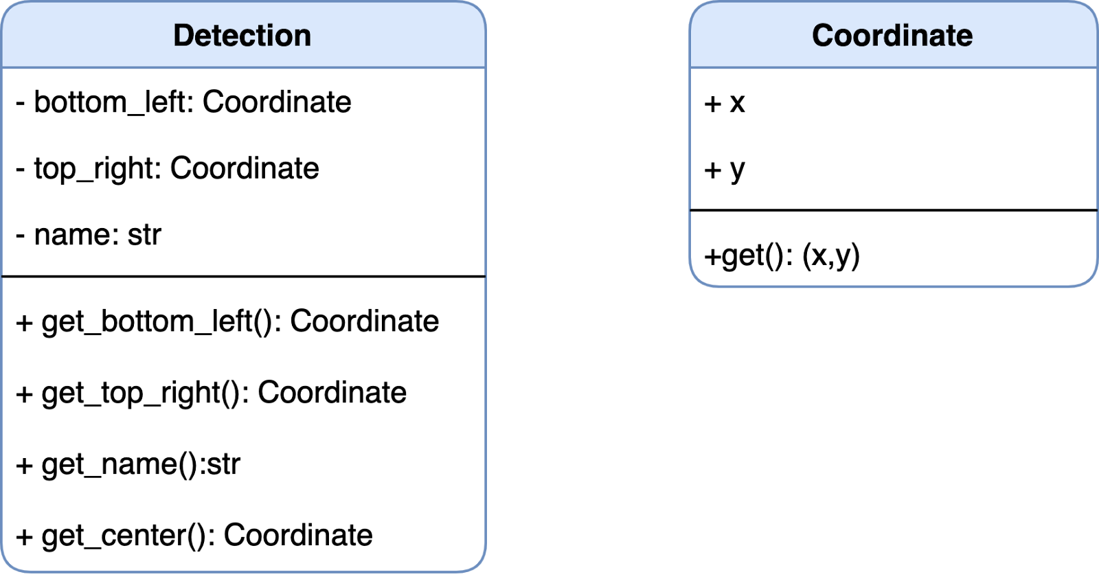
I realized while debugging that the way we handled coordinates in our code was quite dependent on remembering indices. We had our detections in the following format: ((x1,y1,x2,y2), class). Accessing the top right coordinate would be: detection[0][2], detection[0][3], this proved a bit tricky and troublesome when we troubleshooted our threading solution.
So I implemented two classes to ease the readability of our code. So accessing the same coordinate could be done with the following syntax: detection.get_bottom_left().
We have previously discussed using interpolation to “calibrate” our non-linearity when driving our system. If there is shifting friction in the gear system or the bearing system the resulting force exerted from the motors will give different movement. This means that driving the motor with a set number of steps might give us different results due to friction in the system. But if this friction is repeatable at the same spots, we can use interpolation to map out the system’s non-linearity.
This interpolation works by finding the smallest interval for y_a and y_b so that y is between y_a and y_b
The linear interpolation can be expressed as:

Polynimal interpolation uses Lagrange polynomial calculation. This method works by calculating basis polynomial for each value set. These basis polynomials are summed togheter to produce an estimated y-value.

1 2 3 4 5 6 7 8 9 10 11 12 13 14 15 16 17 18 19 20 21 22 23 24 25 26 27 28 29 30 | def __polynomial_coefficients(self, x: float)->list: """Calculates polynomial coefficients Args: x: value Returns: list for coefficients """ n = len(self.__x_values) coefficients = [0]*n for i in range(n): coefficient = 1 for j in range(n): if i != j: coefficient *= ((x - self.__x_values[j])/(self.__x_values[i] - self.__x_values[j])) coefficients[i] = coefficient return coefficients def polynomial_interpolation(self, x: float)->float: """Calculates interpolation polynomial Args: x: value Returns: Interpolated y-value """ coefficients = self.__polynomial_coefficients(x) return sum([coefficients[i]*self.__y_values[i] for i in range(len(self.__x_values))]) |
Source for Lagrange interpolation implementation
Christopher Daffinrud
This week I collaborated with Ole the entire Monday to troubleshoot and fix some multithreading issues that occurred when testing our program on the Pi. Ole has elaborated on this further, so I won’t repeat everything we did.
The rest of the week I needed to prioritize another subject due to an exam submission.
The plan for next week is to finally implement the motor functionalities so that our Detection Model communicates to our motors making the system aim to the target. There will be a more exciting blog post by me next week!
Hannes Weigel
The goal for this week was to find a suitable solution for a barrel with a uniform outer diameter, as well as design a projectile.
The Barrel
The biggest challenge with the barrel is that it has varying outer diameters (OD) throughout its length.
Since we can’t shoot paintball balls (due to bouncing and the paint-mess), we need a custom projectile. This projectile would have to fly straight, and thereby need to be aerodynamical.
The easiest way to achieve this is by having a projectile that slides on the outside of the barrel.
Therefore, the varying OD is a problem.
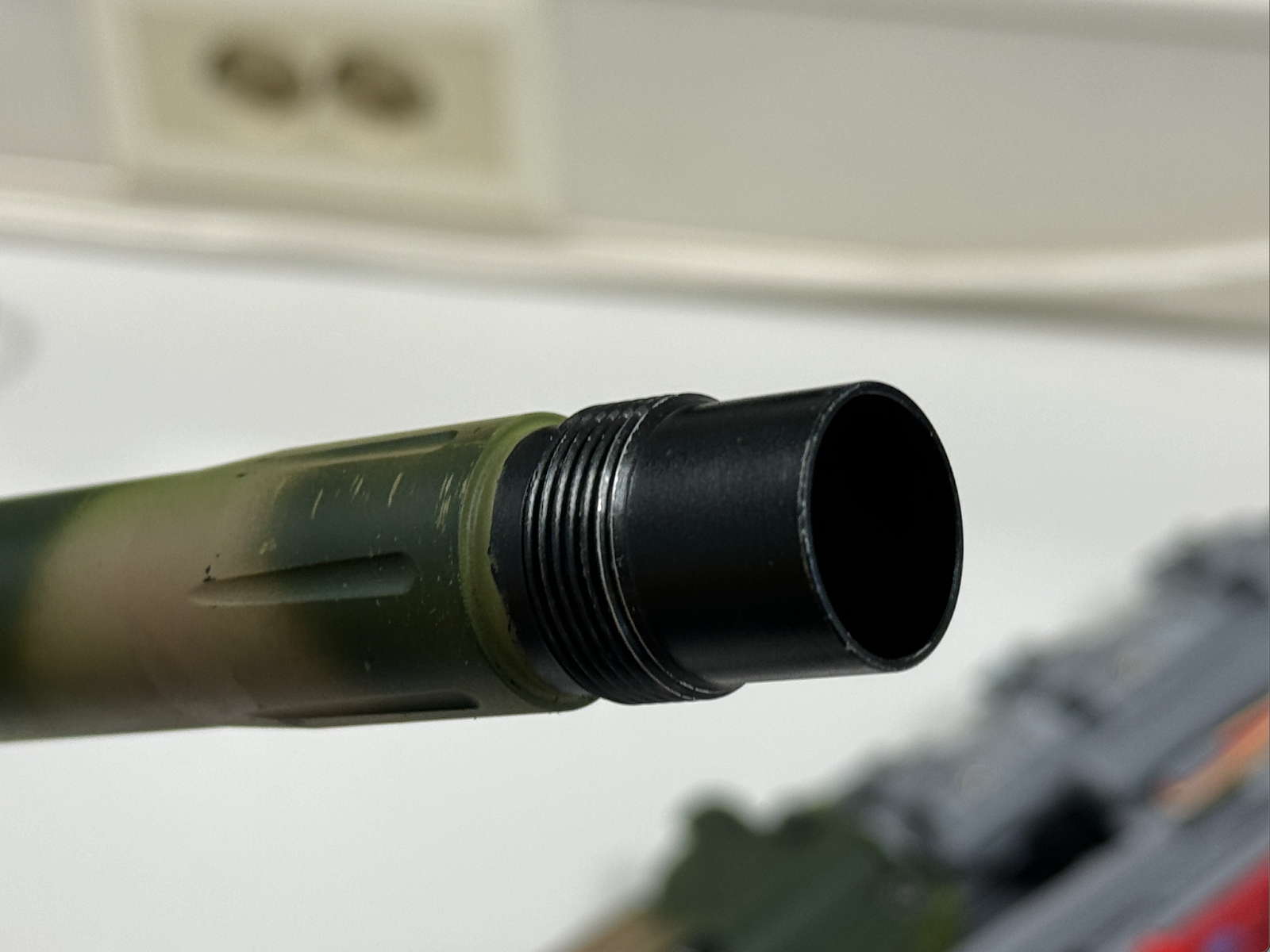
Initially, I wanted to CNC machine a new barrel, but the threads at the end of the barrel deemed this unlikely. The threads were ⅞-20 UNEF, which we don’t have the tools for.
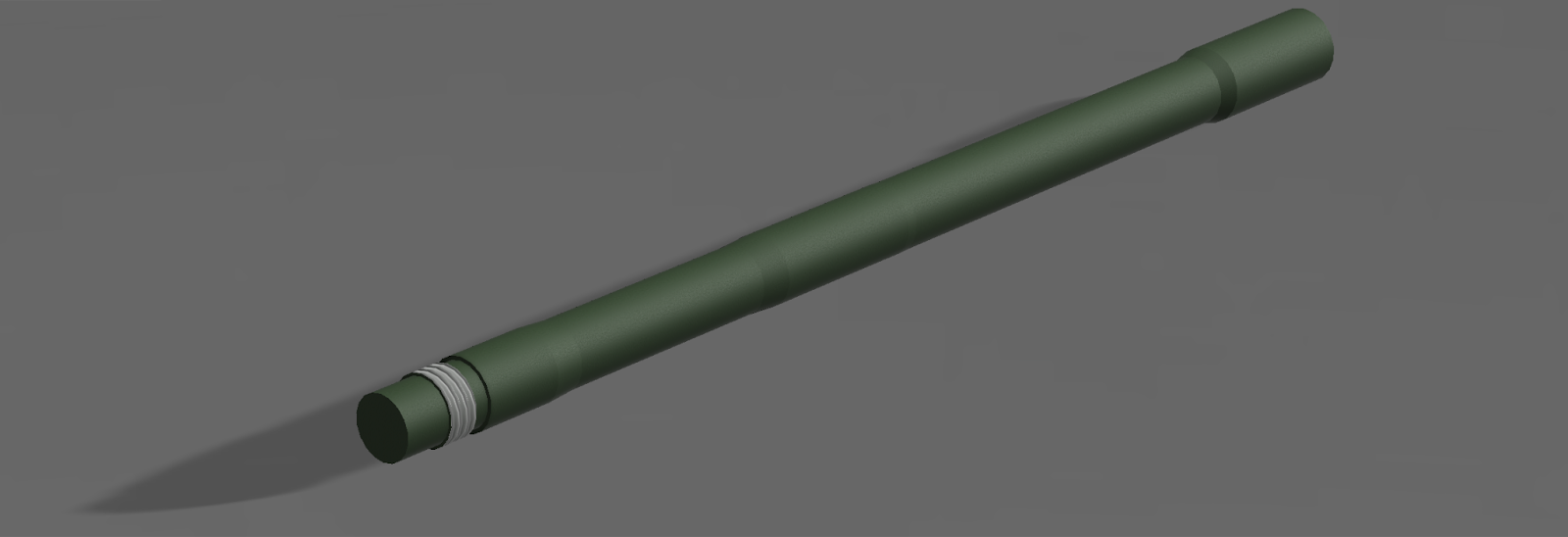
Another approach to this challenge is to manufacture an insert into the barrel that protrudes long enough so that a projectile could be slid onto it.
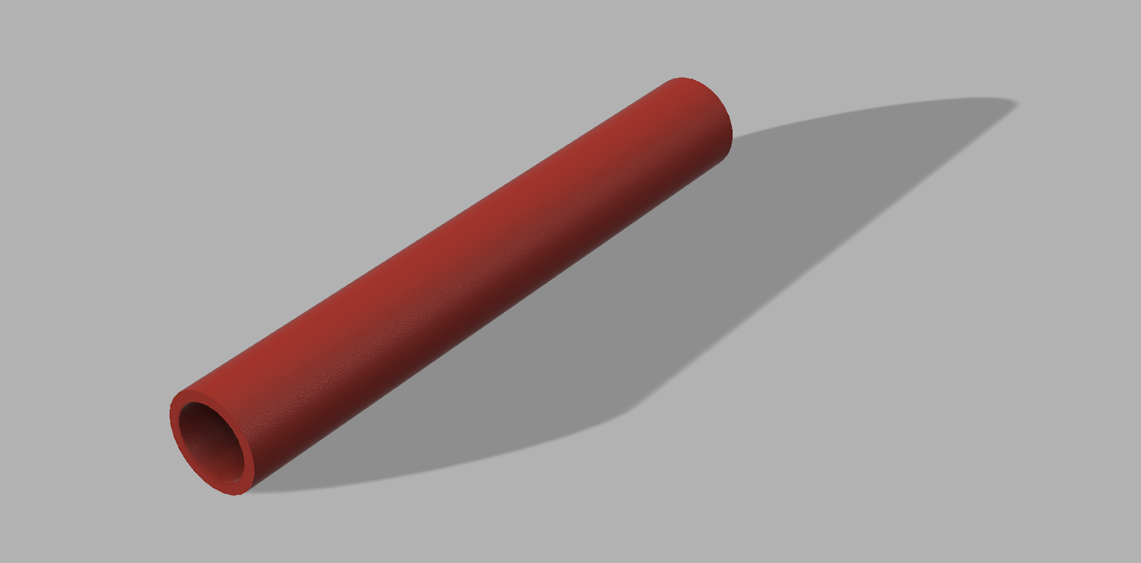
The solution is this barrel extender (yes, it’s just a pipe).
The Projectile
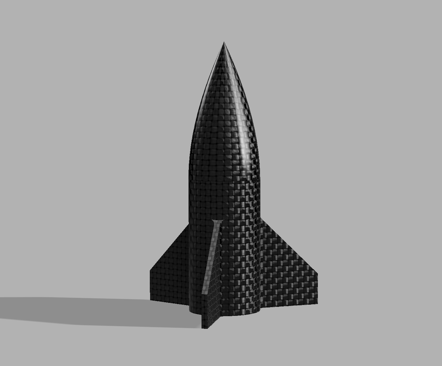
As mentioned before, the projectile would sit on the outside of the barrel (or the extender) such that it could be made aerodynamically stable.
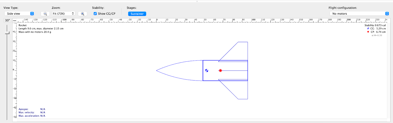
I designed this missile in OpenRocket given the outer diameter of the extender and an estimated length of the entire missile.
For the missile to be stable, the center of mass (center of gravity/CG, here in blue/white) would need to be in front of the center of pressure (CP, here in red).
With most of the mass going into the nosecone, which is an ogive, the CG is biased towards the front.
The fins have to be as large as possible without crossing the CG. This resulted in a trapezoidal fin shape giving the missile a 0.673 CAL stability margin. Not great, not terrible.
As the missile will be 3D printed, the seam between the fins and fin tube need to be reinforced. Here by a 2mm fillet.
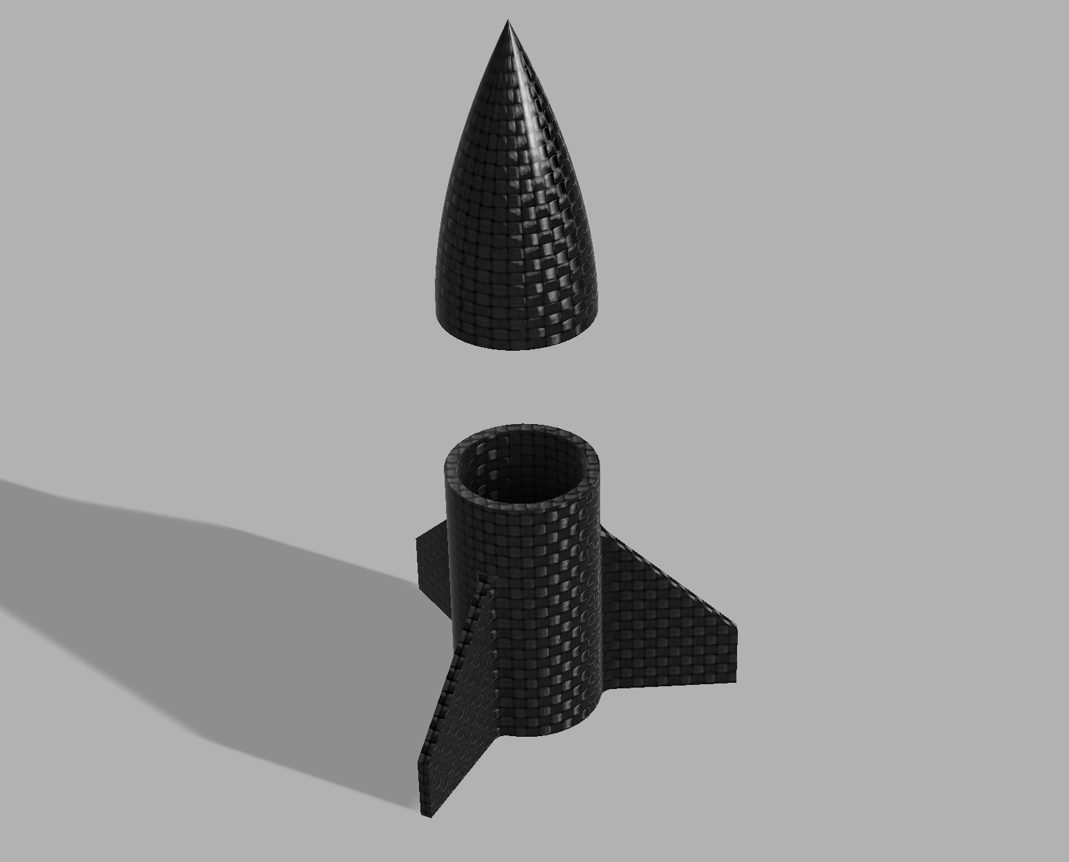
By printing the missile in two pieces, I can ensure that the nosecone is printed more weighty than the fin tube.
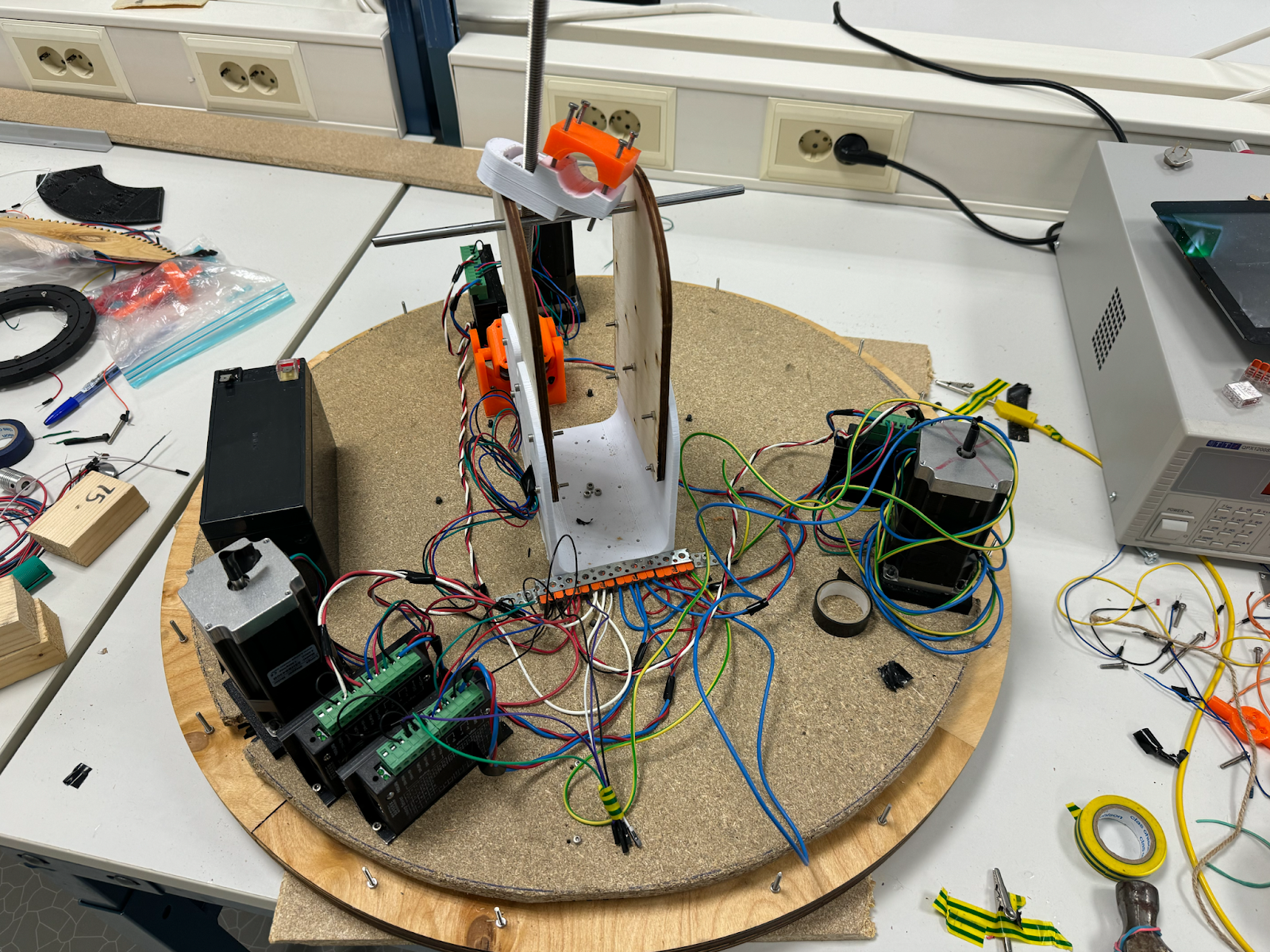
As we have 4 motor controllers, a battery, a camera, a servo motor for the trigger, and a Raspberry Pi that need to be connected, the wiring situation was worse than it is now.
Since several components cross each other several times, the wiring is quite challenging.
Further Work
The entire system needs to be mounted on a more permanent surface. Since we only have about 3 weeks left of the course, the system needs testing to verify that it meets the requirements.
Mats Bergum
Unfortunately, I did not receive the components for the regulator. So, the week went further testing of my 3D printer and learning Fusion 360.
By following these videos:
https://youtu.be/A5bc9c3S12g?list=PL40d7srwyc_Ob77ioP5314_klrB4E0W7x
https://youtu.be/HXRMzJWo0-Q?list=PL40d7srwyc_Ob77ioP5314_klrB4E0W7x
https://youtu.be/zS8dYA_Iluc?list=PL40d7srwyc_Ob77ioP5314_klrB4E0W7x
I made this box:
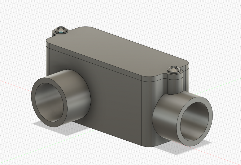
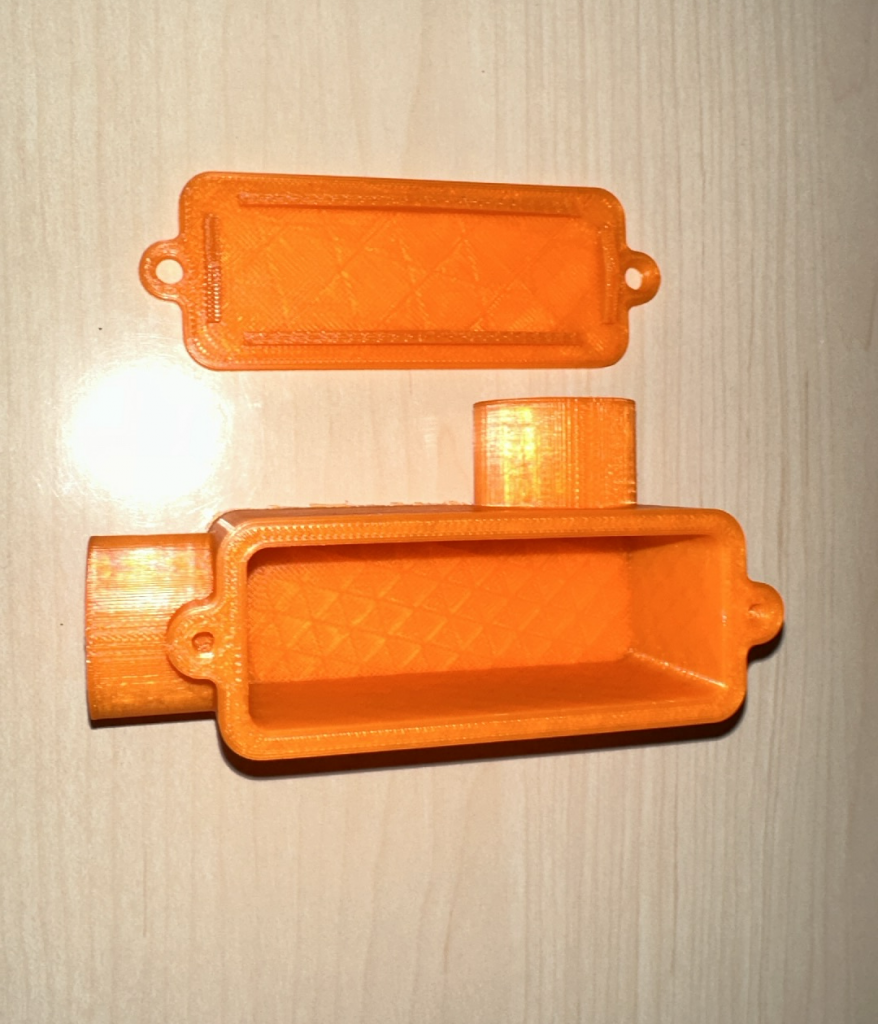
I learned many of the essential functions of Fusion 360 and, most importantly, how to use parametric modeling properly.
Another tutorial that I would recommend for people wanting to learn Fusion 360:
Harald Berzinis
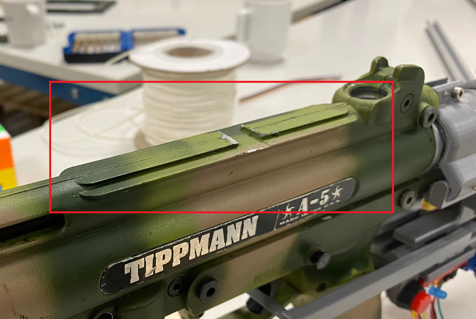
This week I have been designing the new camera mount for the paintball gun. The mount will placed on top of the main rail as showcased in the picture bellow:
Initial CAD-Design
After taking measurements with a caliper tool, I started to look at how I can design a rail that is modular, and that the camera can be shifted to a specific origin if needed. This is to ensure that if there is any needed change to the camera location, I will not be needing to redesign the entire mount. The initial rail that gets mounted on top of the paintball gun became a two part solution as follows:
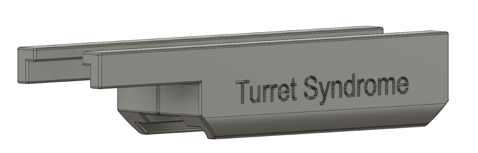
After printing out these two parts, and fitting this to the paintball gun. I found out that the mount fitted very well, so I made a second rail which holds the camera itself. The whole new concept is described in the picture bellow:
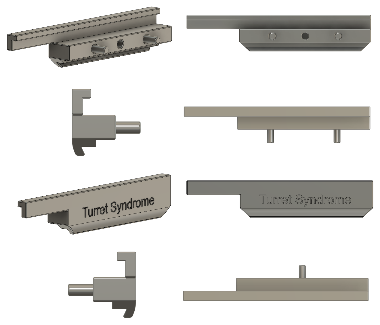
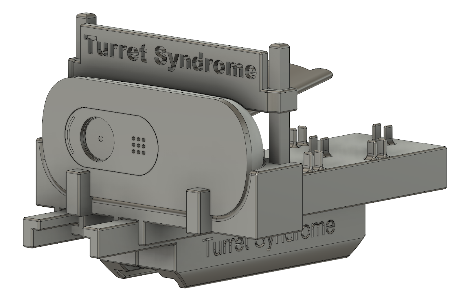
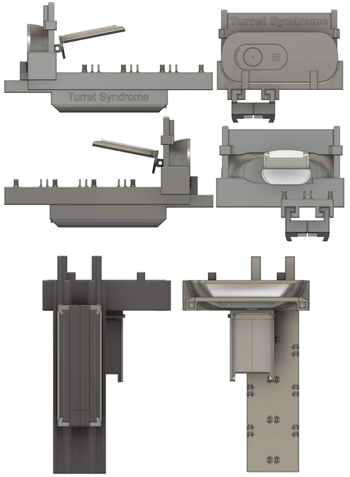
This design is quite modular and the camera mount can be extended outwards to a specific camera origin as shown below:
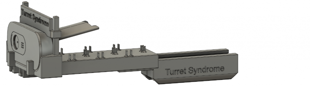
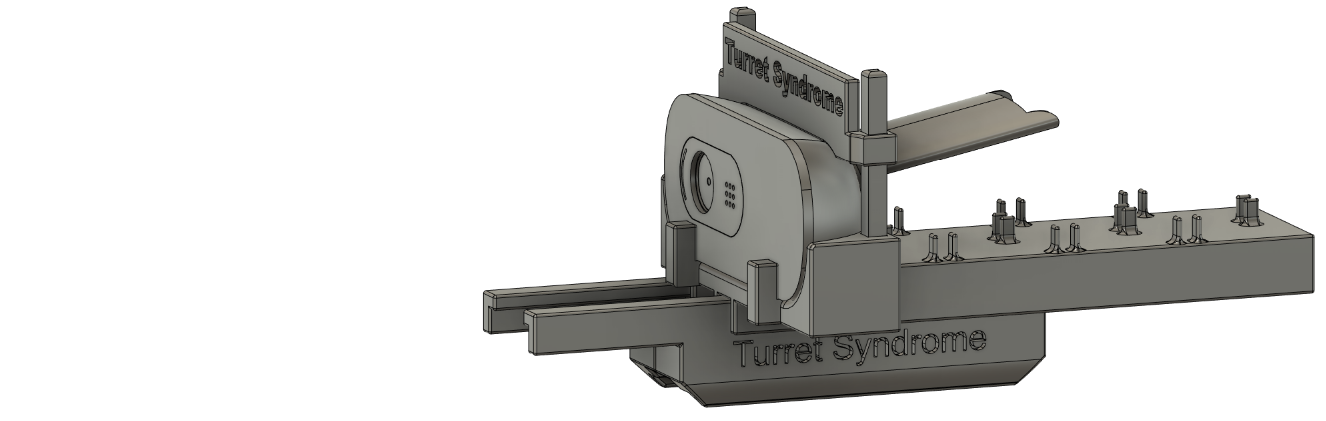
I have also added some small extrusions for cable management, so that the camera cable can be wrapped through instead of hanging in the air. Furthermore, where the camera is placed, there are two rails that hold the camera in place vertically, and two small extrusions that hold it in place horizontally. I have also designed so the gun is in the middle of the camera feed and parallel to the gun, this is to make it easier for the software team and to minimize offsets to ensure accuracy.
Next week:
I will be 3D-printing this contraption fully, assembling it and further testing it.