Andreas
This week has been very unproductive as I was sick for most of it, though I began to feel better this Thursday, so I have been trying to work with smart systems and my exam in PCB design. Despite this, I have tried to assist Bendik in implementing digital filtering with mediocre success. This comes from some bad research before attempting to implement the function. Though I believe we are on the right track now, making a good filter is quite close to accomplished.
Looking at last week’s work I used MATLAB to find the filter coefficients I need to create a filter. I originally began implementing the transfer function directly without considering the plane I was working in, giving us very weird results when testing on the actual prototype. Hopefully, we will be able to implement the new filter function I have found, and with some luck, it will work perfectly.
Until this is done all other tasks are set on the back burner since precise sensory input has to be the backbone of our autonomous movement.
The next week will be spent trying to implement this filter with Bendik, and plan how we will use the rotary encoders, including how we will mount them.
Bendik
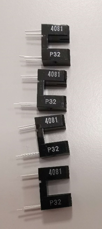
This weekend has been spent soldering the IR sensors, as well as implementing a digital filter with the help of Andreas.
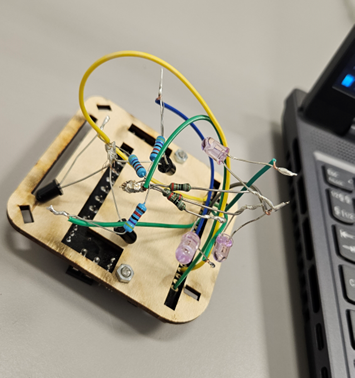
I am aware that the soldering does not look great, but it is a temporary solution until Andreas is able to make a PCB. It functions as it should. The sensors are now soldered directly to the pins on the microbit via the motor driver board.
I tried to implement a band-pass filter using a formula from the book that Jan-Dyre talked about when he gave his lecture on signal processing. This is the formula:
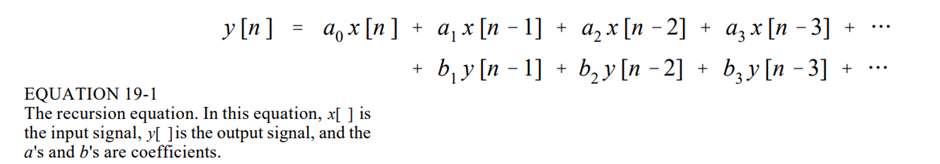
Here the x’es are input values and the y’es are output values.
To calculate the coefficients I had these formulas:
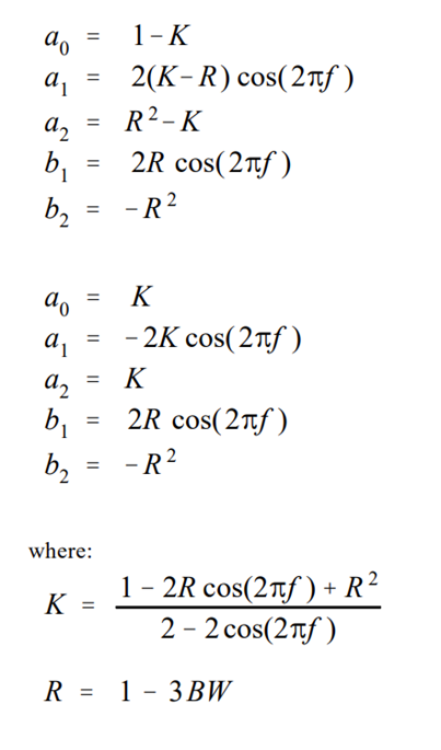
Where BW is the band width that I want to pass, and f is the target frequency. However, using a target frequency of 10 Hz, which the frequency of our IR LED, and a BW of 2, still only gave messy results. I consulted Andreas on this, and he suggested using a 4th order Butterworth bandpass filter and he used MatLab to calculate the coefficients. After implementing, this was the result:
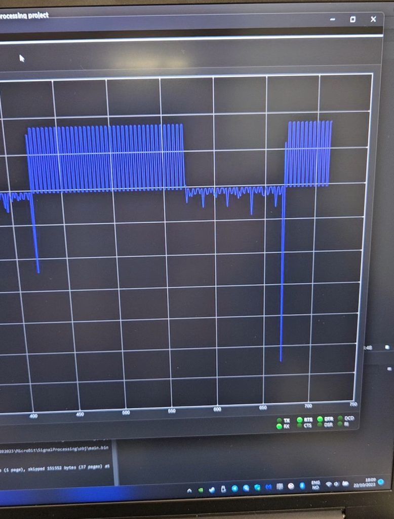
This is much closer to a good filter then we have been before, so I think we are on the right track. That’s it for now, me and Andreas will look closer into this the coming week.
Marte
This week I have been working on improving the wheels grip and started designing the motor encoder.
After having a talk with Richard Monday morning, he gave me a tip to research the use of rubber O-ring to substitute the rings printed in TPU, surrounding the wheels.
I went straight to Tess and found fitting measures for the O-rings by trying them on one of the wheels. I ended up buying 4 O-rings, two for each wheel – and it gave a big improvement in friction.
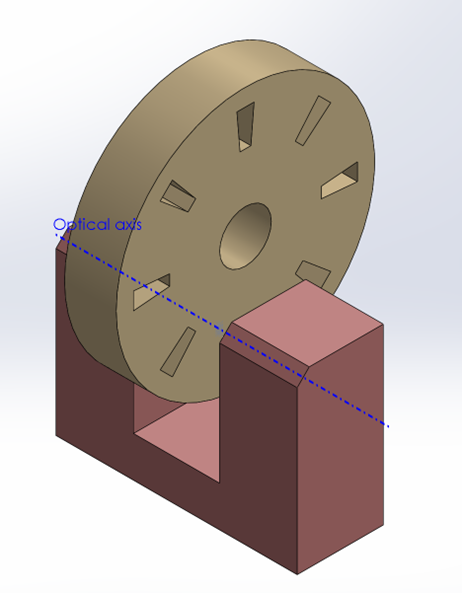
Next on the agenda was to start working on the motor encoder. We want to use motor encoders to obtain information about speed, position and direction. Unfortunately, Andreas was sick this week, but we had already decided on using what optical encoder we wanted to use last week. Steven ordered them last week, and they had arrived already.
Steven gave me a tip about how to deisgn the disc, especially considering how many transparent segments that would be needed. It would be smart to start with a minimum, and later increase if needed.
I then modelled the sensor in SolidWorks, and designed a disc. The disc modelled is only 15mm in diameter and the eight transparent segments are only 2mm in height and 1mm in width. It would be important to have consistency and accuracy in placement of the segments, so after talking with Richard about manufacturing techniques, I will try to produce the disc both with plywood and a laser cutter and with 3D printed PLA. After production we will test and decided which one gives the best result.
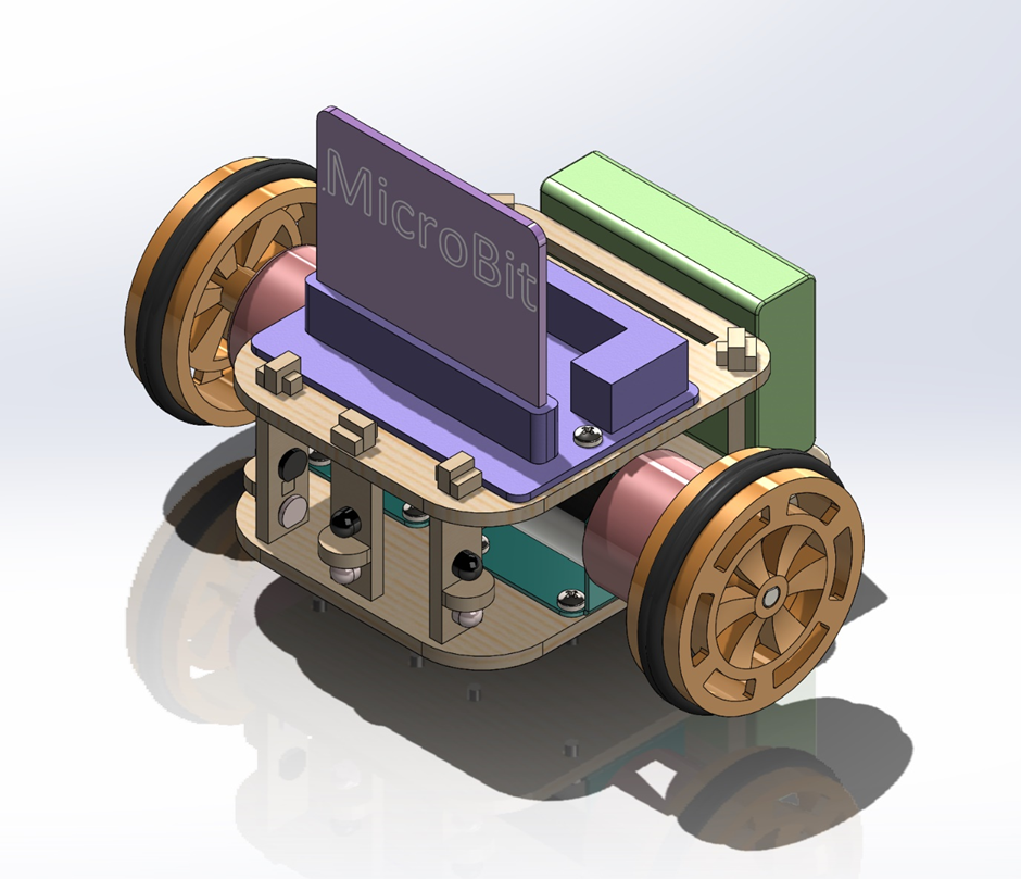
Next week I will continue working with the motor encoders together with Andreas. In addition I will work on a new design for the MicroMouse with smaller motors (we are removing the gear box on both motors).
Vendel
As everyone seemed to have things mostly under control this week, I focused still on the bits to follow the drag race, judging that there wouldn’t be much to gain by being an extra pair of eyes on the digital filters or the motor encoders.
The mouse now can know that it exists, and that there are cells adjacent to it. I broke the code in multiple places trying to implement walls existing, but it has gone back to working again, now with walls, particularly walls preexisting along the perimeters of the maze. Turning the array three-dimensional to fit both the distance from the goal and the wall info broke the pretty display in the console print, but I guess we will just have to deal with that. It’s just a visual aid for us humans after all.
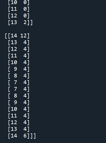
This is the bottom row of the maze, “obviously”. Isn’t it beautiful! Or not.
My reasoning was to use a four bit style encoding, one for each of the walls, giving me a number between 0 and 15 for each cell, representing whether or not it had a wall in the given orientation, zero being no walls, then in binary going from left to right: west, south, east and north. In Python this is done with integers, but the hope is to do this all the way down at the bit level in an optimal implementation, with the data of each cell fitting in 12bits, one byte for the distance from the goal(an integer up to 255), and a nibble for the wall data. Considering the space we have available on the Micro:Bit however, this isn’t a major concern. Could the map take less than a kilobyte of space? Sure, but with several megabytes of available space, making it work at all is far more important than making it fit in the smallest possible space.
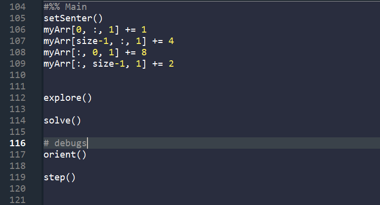
Deceptively simple, isn’t it? Hopefully it will stay that way, but there is plenty of code hidden behind the functions. Some of it I’m suspecting is needlessly complicated.
But the long and short of it is that the map now has the capacity for walls, and I have outlined a filter to check for the walls being there or not, making both exploration and pathfinding possible.