Hi Dronesonen! 😊
Last week we conducted the following efforts:
Discipline – Software:
Erik-Andre Hegna:
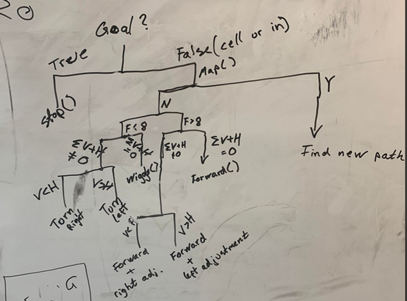
Monday was spent with Lars and Ask to map the logic of our micromouse on a whiteboard. By that I mean, in what order things are completed/terminated, and depending on what is happening with the sensors the mouse will make decisions accordingly.
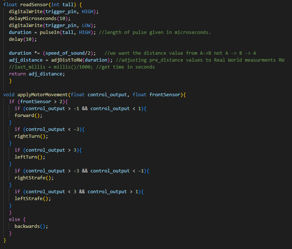
Wednesday was spent on creating the PID regulator using the left and right side sensor. It is supposed to make the mouse able to hold and auto correct its path inside the maze. As geometrical size will change once the PCB arrives, I have not been able to calibrate the movement and adjust correct motor movement for optimal movement through the maze. But the mouse was able to autocorrect its movement to a certain degree:
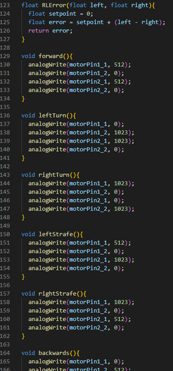
This is the code i created:
Needed functions:
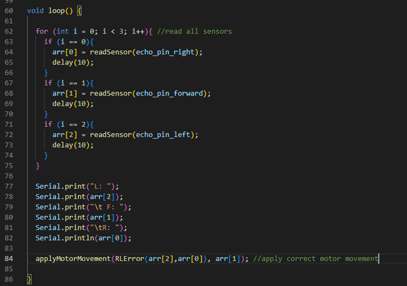
Main loop:
Lars Leganger:
On Monday I worked on the structure of the mouses movement. We set up diagram on how the mouse will move and what it should prioritize based on how we want it to move.
On Wednesday we started to take measurements to use in the driver functions of the mouse. We decided to wait because we think we can get even more accurate data from the sensors.
I worked on ways to solve the mapping problem for the mouse.
Ask Lindbråten:
On Monday, the other software guys and I decided to have a theoretical discussion about the conditions the micromouse must validate before conducting actions in the maze, since we had to wait for some electrical and mechanical changes before we could conduct more practical tests. Additionally, we also discussed what specific motor control functions are needed to perform these actions. We began by writing a rough check-list, before I had to leave for my usual mandatory work. But later I was informed that Erik-Andre and Lars decided to create a small tree-graph instead, since it made it a lot easier to visualize all the possible outcomes of the conditions in the check-list.
On Wednesday, my main goal was to hopefully verify that the “listening to port and writing to text files” – script I created last week would work and start running measurement tests for cm’s between 0 to 50 to find an improved best fit linear function to adjust measurements to real world distances. We realized that we had to adjust our “driving forward” – range to > 50, since having it set to > 20, left us with little time to make any necessary adjustments, should we for instance encounter an obstacle at a distance of 21 cm from the front/middle sensor.
However, After a brief update on the PCB with Hugo, we decided to halt the entire measurement test until we receive the PCB. The possible changes to the sensor’s placement, connections and noise as a result of a cleaner setup would most likely result in me and Lars having to run the entire measurements test a second time under the final test conditions, which would be quite time-consuming and unnecessary. But we still wanted to verify that the script would work as intended, so we can start the practical tests as soon as the PCB arrives. Me and Lars tested it for a few cm’s, and it worked! 😁 Finally!!
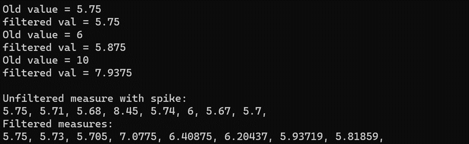
After that, I talked a little bit with Erik-Andre on how he visualized we could apply the lowpass-filter to our project. We want to apply it for singular values and return a single filtered value based on the previous filtered value, instead of a filtered data set. The script I created and added below does exactly that. Bear in mind that the constant values for the strength variables, which decides if the new filtered value are closer to the previous filtered value or the measurement, are just examples and have to be adjusted after further tests and discussions with the group. There is pros and cons with increasing or decreasing both, but we have to find what works best for us.
double adjLowPass(double arr[], double nv_strength, double oldv_strength, double x);

int main()
{
	double prev_val_arr[1] = { 0 };
	double new_val_str = 0.5;
	double old_val_str = 0.5;

	double measure = 5.75;
	double filtered_measure = adjLowPass(prev_val_arr, new_val_str, old_val_str, measure);
	std::cout << "Old value = " << measure;
	std::cout << "\nfiltered val = " << filtered_measure;

	measure = 6;
	filtered_measure = adjLowPass(prev_val_arr, new_val_str, old_val_str, measure);
	std::cout << "\nOld value = " << measure;
	std::cout << "\nfiltered val = " << filtered_measure;

	measure = 10;
	filtered_measure = adjLowPass(prev_val_arr, new_val_str, old_val_str, measure);
	std::cout << "\nOld value = " << measure;
	std::cout << "\nfiltered val = " << filtered_measure;

	prev_val_arr[0] = 0;

	double measures[8] = { 5.75, 5.71, 5.68, 8.45, 5.74, 6.00, 5.67, 5.70 };
	const int size = sizeof(measures)/sizeof(measures[0]);
	double filtered_measures[size];

	for (int i{ 0 }; i < size; i++) {
		filtered_measures[i] = adjLowPass(prev_val_arr, new_val_str, old_val_str, measures[i]);
	}

	std::cout << "\n\nUnfiltered measure with spike:\n";
	for (int i = 0; i < size; i++) {
		std::cout << measures[i] << ", ";
	}
	std::cout << "\nFiltered measures:\n";
	for (int i = 0; i < size; i++) {
		std::cout << filtered_measures[i] << ", ";
	}


}

double adjLowPass(double arr[], double nv_strength, double oldv_strength, double x)
{
	if (arr[0] == 0) {
		arr[0] = x;
		return arr[0];
	}
	else {
		double filtered_x = arr[0] * oldv_strength + x * nv_strength;
		arr[0] = filtered_x;
		return arr[0];
	}
}
Running this script gives the following results:
Discipline – Electrical:
Hugo Valery Mathis Masson-Benoit:
The objective for this week was to finish the design of the PCB, and do the testing for the magnetic sensors.
Magnetic sensors:
Unexpectedly, I needed to do myself the testing for the implementation of the magnetic sensor. So, I tested them to see how they would react in a circuit. After some time and the help of Mr.Bos, I’ve realized that a pull-down resistor is needed to make the magnetic sensor switch.
The final design for the implementation of the sensors was this:
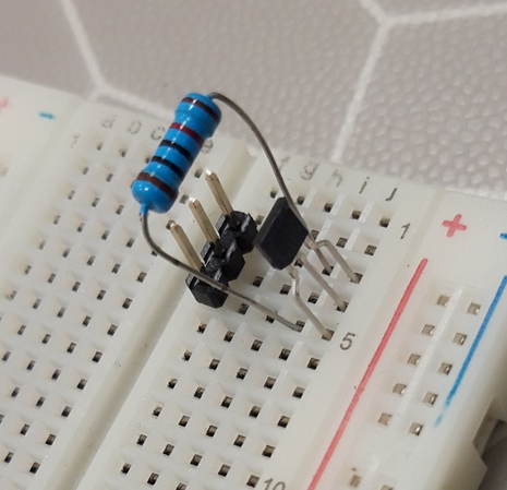
To make everything work, the polarity of the magnets needs to be altered on the wheel like this : one South pole, one North pole, one South pole, etc … So, the sensor will switch between an high state and a low state each time it encounters a magnet.
I’m going to write a document to show the mechanical engineer how to implement the magnets.
PCB design:
The PCB design is finished. I’ve checked with the mechanical engineer to confirm that the design was good for her and that she had the place needed to work with to fix the motor and other mechanical part.
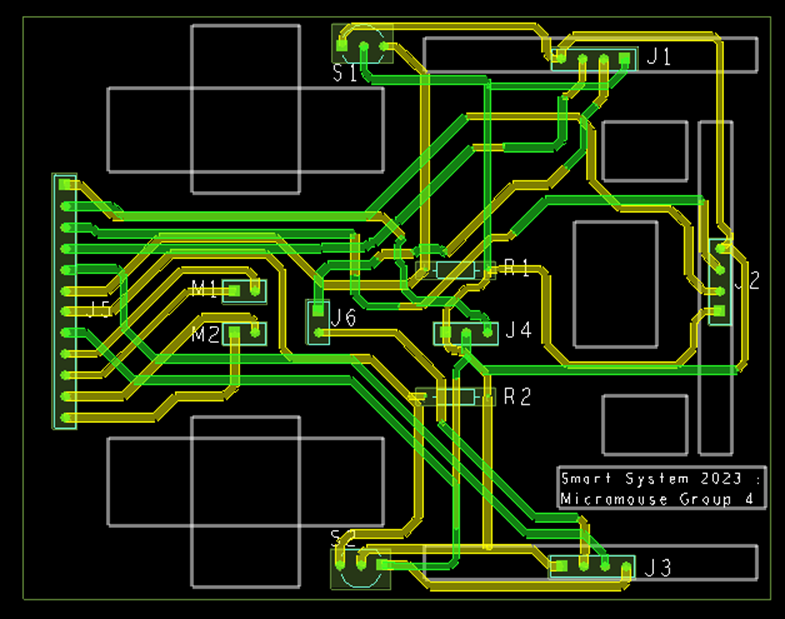
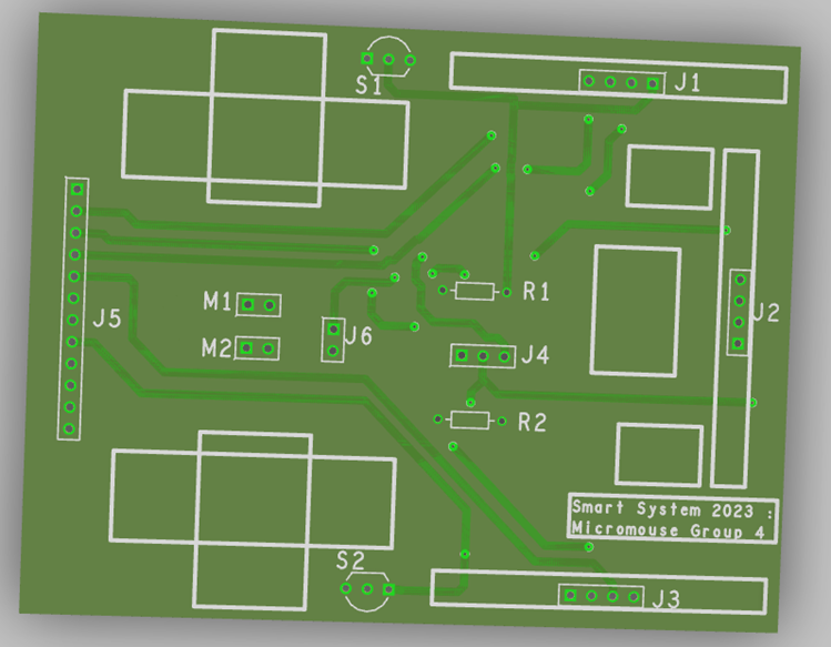
The PCB was commanded the 26/08/2023, so it should be delivered for the next week.
Conclusion:
The magnetic sensors are tested and implemented, and PCB is done, approved and commanded.
Objective for next week:
I’m waiting for the delivery, then I’ll solder all the component and I’ll be finished for my part.
Jemima Niquen Tapia:
This week I prepared the prototype for the rice drag, finally fixed the code problem and it worked as we planned.
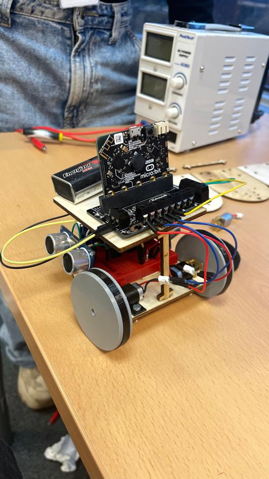
Then with the mechanical engineer we prepared the next prototype too. We connect the new motors and the regulator as we have 9V motors now, and they are little. The software team needed the connection of the motors and the sensors to do some calibration, so we did a quick adaptation till we didn’t have the PCB. In the picture we can see the final result.
Discipline – Mechanical:
Cesia Niquen Tapia:
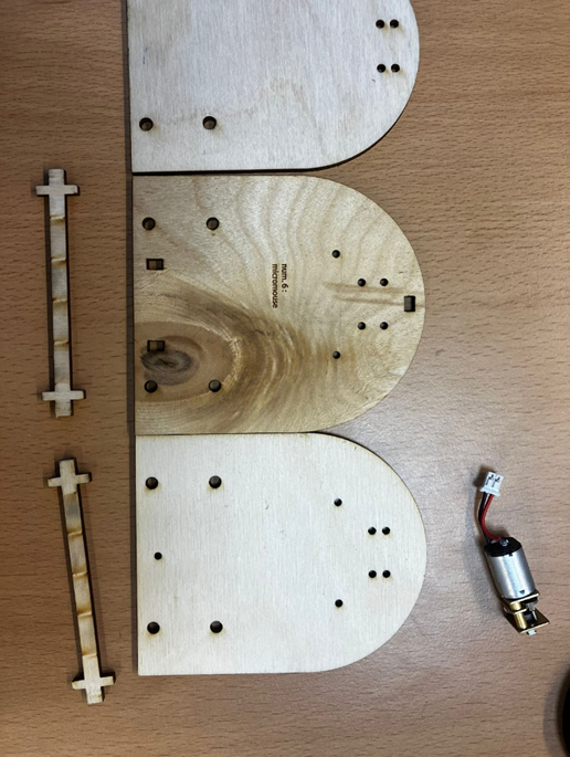
This week in order to have a functional prototype I designed a quick second floor with the laser cut. This was needed since the last 3D printing failed. This laser cut assy was made in order to start with the testing, and meanwhile we wait for the pcv.
There was also a redesign with the wheels, in order to make them fit better in the engines, improving the traction and movement of the micromouse.
This concludes our blog post for week 10, see you next week!😊