Hi Dronesonen! 😊
Last week we conducted the following efforts:
Discipline – Software:
Erik-Andre Hegna:
Monday:
This week I spent more time on the PID. As I have already used a lot of time researching the mechanics and algorithms behind the software, I now started developing it with code. As of now, I am developing it to use the right side sensor and the left side sensor to find the middle value (Optimal: left side – right side = 0). This way we can make the micro mouse stay on course by adding motorspeed on either right side or left side to get it back on track if it strays from the middle.
After discussions with Steven and other classmates I figured the P in PID is enough for us, but I will debate this with the rest of the group on monday. When using the PID in the micromouse, we need to add additional features in case there is only a wall present on either side → ignore using PID when a good sensor reading is received, or some other solution.
Wednesday:
the rest of the group met up, but I had to meet with my game design group. I came in later in the day to see their progress. This time was spent on fault-testing the dragrace code, and trying to make the micromouse run.
Lars Leganger:
This week I worked on the drag race code and the filter for the sensors. The code for the drag race has three functions. its full speed, reduced speed and stop. We already have a forward and stop functions in the code so I made the reduced speed function so the mouse can begin to slow down when it closes the wall so it dont crash. Here are the extensions I made to the driver code.
void mediumSpeed() {
  analogWrite(MP1_1,225);
  analogWrite(MP1_2,0);
  analogWrite(MP2_1,225);
  analogWrite(MP2_2,0);
}

void loop() {


double SensorRead = readSensor();
delay(50);


if(SensorRead > 40){
  driveForward();
}
if(SensorRead > 20 && SensorRead< 50){
  mediumSpeed();
}
if(SensorRead < 20){
  stop();
}


delay(50);
I also worked on the low pass filter. We tried to implement the code example jan dyre had in his presentation, but we faced a lot of problems. We tried to use vectors for our filter but the vector library in VS code wouldn’t work. We switched over to arrays but it wouldn’t work. Next week I will continue to fix the problem. This is the current low pass filter.
pre_distances[count] = SensorRead;

 count++;

 double* filtered[1] = lowPassFilter(pre_distances, new_val, old_val); */

}

double* lowPassFilter(double pre_distances[], double new_val, double old_val){

    double* result = new double[sizeof(pre_distances)/sizeof(pre_distances[0])];

    for (int i{0}; i< sizeof(pre_distances)/sizeof(pre_distances[0]);i++){

        result[i] = pre_distances[i]*new_val + result[i-1]*old_val;

    }

    return result;

}
Ask Lindbråten:
I’d like to start my blog-post by stating that I’ve been heavily focused on my contributions to the game design document for game development this week, so I haven’t been able to work as much with smart systems. Nevertheless, I set a small goal to hopefully finalize a solution for reading values from the communication port and writing them to text files, since I’ve been striving to achieve this for weeks. This way we can plot a lot more points in GeoGebra and improve the accuracy and applicability of the linear approximation function (used for converting measurements to RW distances) I found in week 8.
On the basis of many debug errors and unsuccessful attempts to do this in VS code, along with my late realization that the arduino library is not as extensive as the standard C++ library, I decided to try to configure a solution using Visual Studio. My idea was to create a script that reads values from a COM port and appends those values to a text file using the simple fstream library. Initially I tried to use the windows.h – library to create a HANDLE and DCB object, read the incoming bytes through the function ReadFile, add them to the data-array, and later on convert the elements in the data-array to strings using stringstream and append them to the text file. While I actually managed to append the incoming values to the text-file and see the incoming bytes in the monitor this time, the script still gave me some unexpected results as it was just the same four values being appended in a constant loop. So, after a good amount of troubleshooting with no luck unfortunately, I discarded this idea and discovered another potential solution using a combination of both CLR (Common Language Runtime)- and standard C++ code. The script is added below:
#include "pch.h"
#include <iostream>
#include <fstream>
#include <msclr/marshal_cppstd.h>
#include <Windows.h>


using namespace System::IO::Ports;

int main(array<System::String ^> ^args)
{
    std::ofstream outputfile;
    std::ofstream RW_value;
    outputfile.open("value_file.txt");
    RW_value.open("RW_value.txt");

    SerialPort port("COM4", 115200);
    port.Open();

    int elem_counter = 0;
    int max_counter = 10;
    int active_cm = 1;
    int delay_ms = 1000;

    while (elem_counter < max_counter) {
        System::String^ data = port.ReadLine();
        if (data->Length != 0) {
            std::string dataStr = msclr::interop::marshal_as<std::string>(data);
            outputfile << dataStr;
            RW_value << active_cm;
            std::cout << "Data appended: " << dataStr << "\n";
            elem_counter++;
        }
        else {
            std::cout << "No data received\n";
        }
        Sleep(delay_ms);
    }
    outputfile.close();
    RW_value.close();
    port.Close();

}
The idea here can be roughly summarized as follows:
- Establish a port connection for listening.
- Read the incoming value and store it to the variable -> “data” with type System::String (targeting the .NET framework).
- Convert the value of the data-variable to std::string (applicable for appending to the value text file).
- Append the std::string equivalent value to the value file, add another instance of the active RW distance being measured to the RW_value file and increase element counter.
- The while loop reads every second, and appends a number of values (set in the variable “max_counter”) to the value file, along with an equivalent number of instances of the RW distance to the RW_value text file. When the element counter (elem_counter) is equal to the max_counter, the while loop breaks.
In simpler terms, let’s say I’m measuring for the RW distance = 1 cm. The outputfile would then be filled with 10 ultrasonic sensor measurements (x), while the RW_value file would be filled with an equivalent number of one’s (y). This way we can plot 10 * (x,y) coordinates. Obviously, I haven’t been able to test this practically, but I’m hopeful I’m able to finally succeed with this in the upcoming week(s). Fingers crossed 🤞
Lastly, I also managed to adjust Jan Dyres lowpass code to work with vectors in Visual Studio. Maybe were able to run the measurements through this filter to remove the extremes before we plot them to get an even more representative linear function. These configurations would have to wait for now though, but below is the added script:
std::vector<double> lowPassFilter(std::vector<double> pre_distances, double new_val, double old_val){
    std::vector<double> result(pre_distances.size());
result[0] = pre_distances[0];
    for (int i{1}; i < pre_distances.size();i++){
        result[i] = pre_distances[i]*new_val + result[i-1]*old_val;
    }
    return result;
}
Discipline – Electrical:
Hugo Valery Mathis Masson-Benoit:
The objective for this week was to start the PCB design.
This week I did the design of the PCB where we’re going to put all the sensor and motors. I took in account the area needed for the motors, their fixation, and the size of the three ultrasonic sensors.
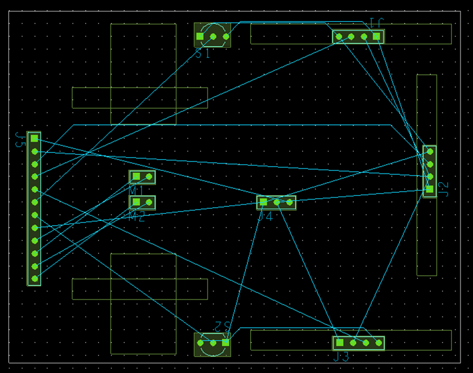
You can see on the right side the square representing the ultrasonic sensor, and on the left the area reserved for the motors and their fixation.
I’m waiting for the feed back of the mechanical engineer to be sure that the place and the size of the PCB is good for them, and the results of the test concerning the magnetic sensor to know how to turn them.
Conclusion:
The PCB is almost done, I just need some validation to finish and command it.
Objective for next week:
Get the approval from the other member of the team, finish and command the PCB.
Jemima Niquen Tapia:
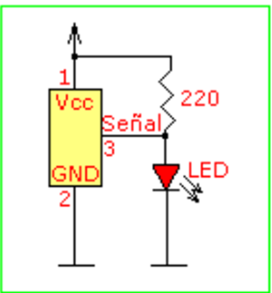
This week I have been working on the magnetics sensor, as we received it on Tuesday, I tried to check the sensor with an Arduino One and see the data, we used a simple circuit as we see in the picture. At the moment the sensor sends the whole time a 1, like if the whole time it detects a magnet. It’s a problem that still needs to be solved.
Also we have prepared our micro mouse for the Drag race, as we are going to use the other motors. So we welded some wires at the motors and connect it to the board, and also put a simple program, and we tried the micro mouse, we found some problems as we thought it was a current problem, but after some research looks like it was the board that make the input pin in the voltage regulator was unclear. After solving some other things it should work, but we still have to do some changes.
Discipline – Mechanical:
Cesia Niquen Tapia:
This week I focused in the structure of what is getting closer to our final prototype. The design of the second floor has the purpose of saving some space since this new design is way smaller than the other. This new base it’s 7×9 cm.


The size of this new element is ready to stand the battery and the microbit, putting them up there we also make them an easy access.

This concludes our blog post for week 9, see you next week!😊