Christopher Daffinrud
Following up from last week, Ole and myself sat down to discuss, figure out and come to a viable solution for data-sharing between threads and objects in our software.
We found out that creating a class for our wanted shared-variables, camera frames and coordinates, and using Threading.Condition() for synchronizing and avoiding race conditions between objects would work when reading and writing from the same resource.
We used our Monday to verify that this method would work before starting to implement our different subsystems and tying them together.
Some of our previously written code was a bit too compartmentalized and hard to tie together. Therefore we divided the tasks between us, both restructuring code into OOP and structuring it around our newly found method of data-sharing:
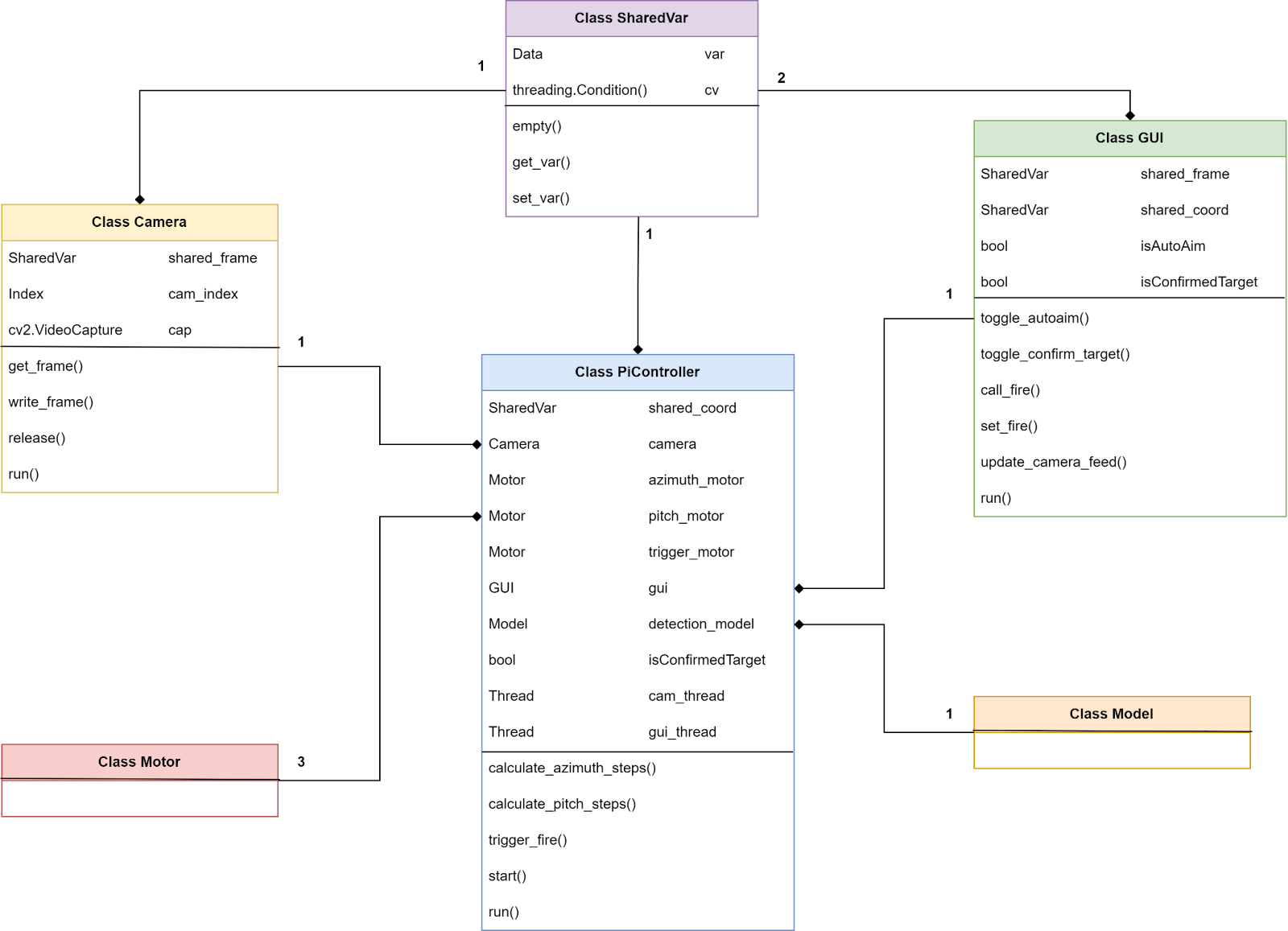
I restructured / implemented the following classes based on the principles shown in the diagram above: Sharedvar, Camera, GUI and PiController.
In the diagram our PiController-class works mainly as an initializer of objects and threads sharing resources through Condition objects. It will also function as a computing brain for calculating the necessary steps for our Motors.
The code now works by sharing camera frames between the CameraFeed and the GUI through Condition objects.
Next Week:
Continue to focus on implementing our software in a way that makes it fit for testing our system as a whole. There are some things needed before this though:
- Sharing coordinates between Model and PiController
- Threading for Motor-handling in PiController
- Editing the Motor-class for initializing azimuth, pitch and trigger motor
- A main for running the software as a whole
- Functions in PiController that calculates the relationship between pixel coordinates and steps for motors. This needs to be mapped out in testing.
Ole Eirik S.Seljordslia
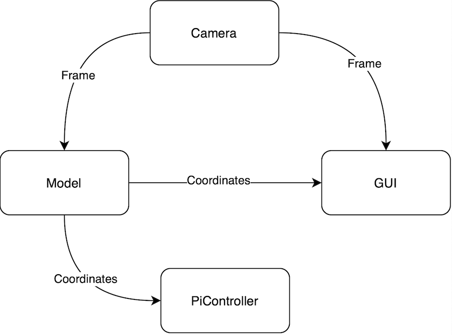
As Christopher mentions; We worked on deploying multiple threads with synchronized data sharing to achieve concurrency for our system. We knew that we wanted one thread that would produce frames from a camera stream. The frame produced is then consumed by two threads: one model thread and a GUI thread. Additionally the model thread should produce coordinates for GUI and PiController. All this data writing/reading between threads needed to be synchronised.
This dependency meant that we needed some sort of synchronizing mechanism. We tested different implementations for Python. But we ended up using a conditional variable, the usage seemed quite straight forward and when we tested our proof of concept of data sharing; the conditional variable proved satisfactory.
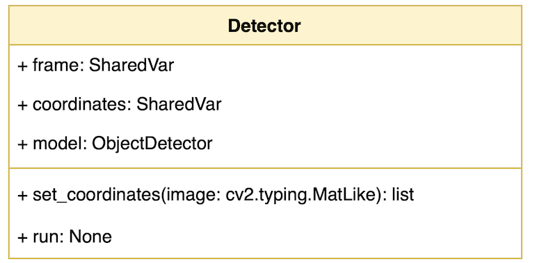
The model thread will be encapsulated in a class called Detector. The model class has two shared variables: frame and coordinates. These are shared between the PiController and GUI threads.
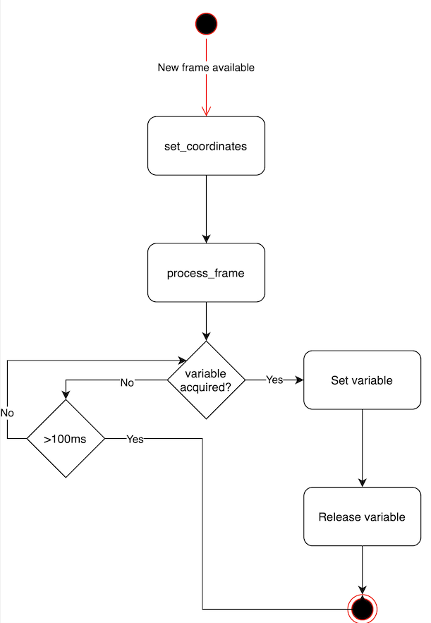
The behavior of the model class is quite straightforward. When a new frame is received, it is processed and coordinates are produced if there are any detections. Then the class will try to acquire the shared coordinates variable, if it’s successful within 100ms it will write to the variable then release it. If not it will start trying to process a new frame. At this point we accept that we did not process the frame in time and it’s more reasonable to process a new frame.
Next week:
- Test our threading/synchronization solution
- Optimize for performance
- Wrap coordinates in class
- Interpolation for motor step mapping
Harald Berzinis
This week I have been continuing my work with the trigger mechanism, and it is now fully functional! Furthermore, I have been designing a new component to the mechanism, where its purpose is holding the button-switch, bread-board, LED diode, 1k ohm resistor and couple of wires.
Bread-board Holder:
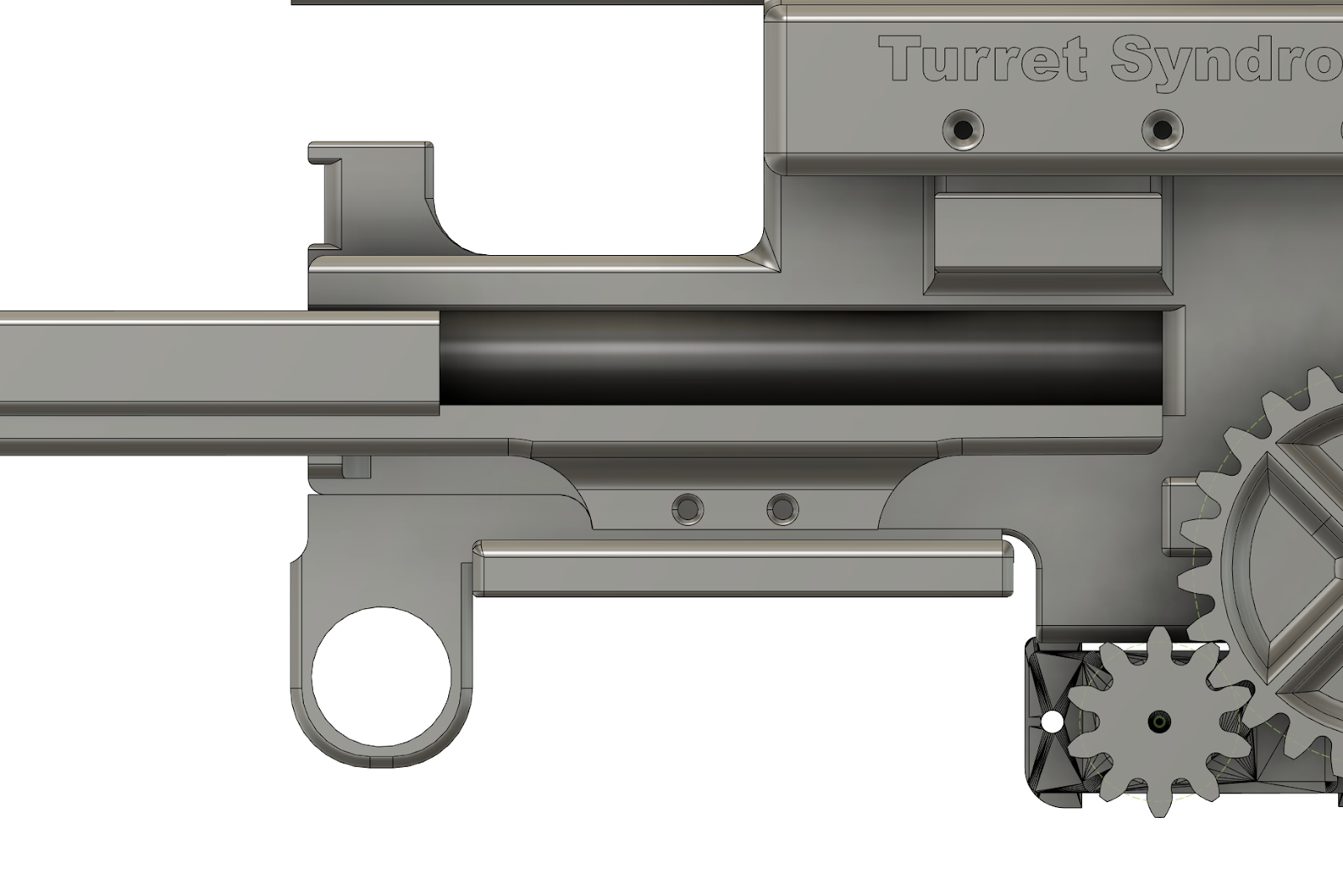
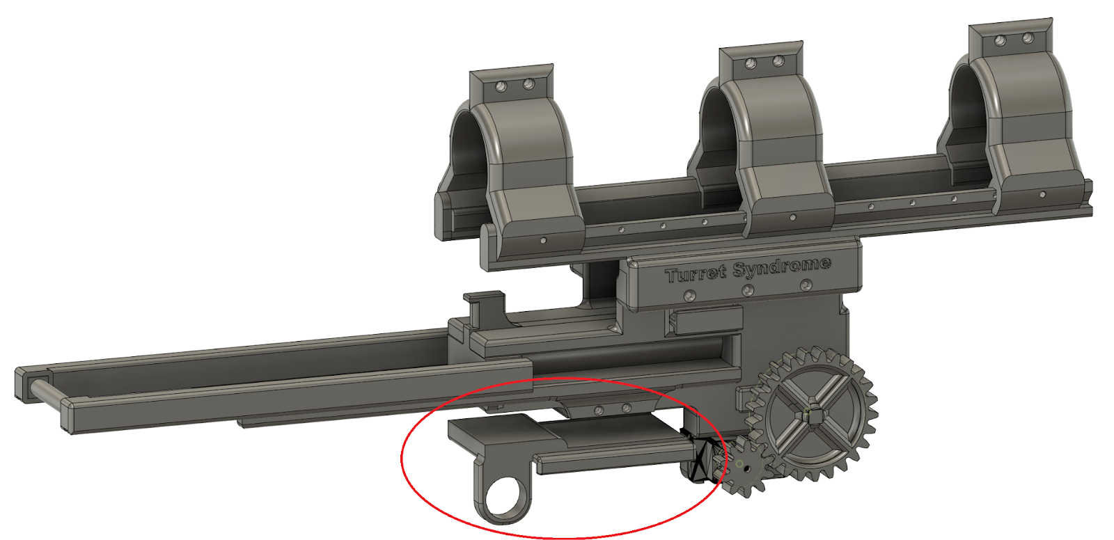
The new component is marked in red, and fits snuggly against the main body.

Here is the component from different views.
Assembly
I printed this component at 30% infill and glued it with superglue. The hole and the dimensions of the enclosure fit the bread board and button-switch with no additional sanding. After assembling, I started to design a circuit which works by pressing the button-switch. The purpose for this simple circuit below is to make the loading of the mechanism much easier and to show with a led-diode that the contraption is ready to be reloaded. I used an Arduino Mega, to test the idea. At the end of the project this will be replaced with the main Raspberry Pi instead.
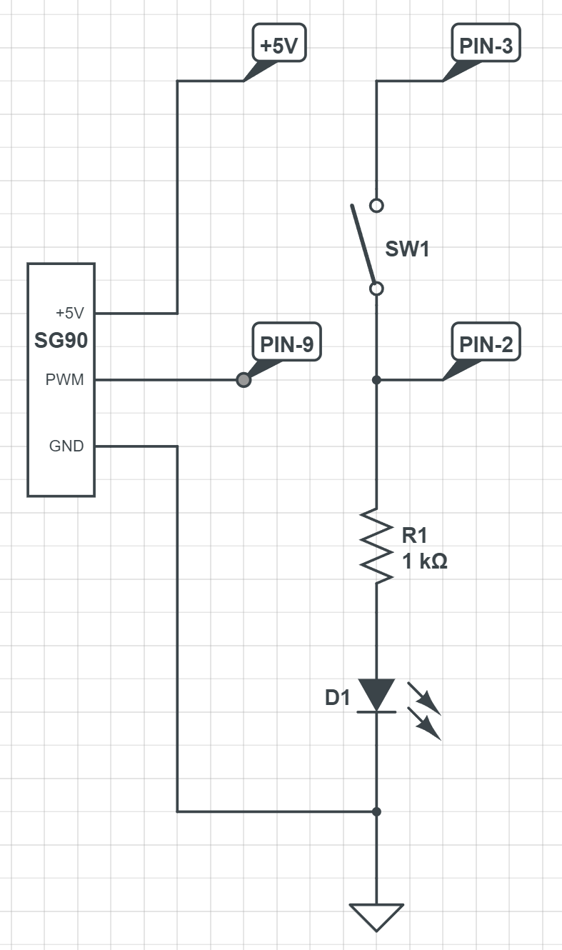
The current circuit for the mechanism, with output and input pins for Arduino Mega.
Testing
Here is a video showcasing the first iteration of the functioning mechanism:
This is the second video showing the mechanism mounted together with the paint-ball gun. As you can see we needed to use some duct tape to increase the friction between the buttstock and the mechanism itself. This is due to the fact that the force being applied through the rubber bands against the trigger slides the entire contraption. This was quickly fixed with some duct tape and resulted in a more stable outcome. I also needed to fasten the existing bolts on the rail mounts. I further improved the cable management of the circuit from the first video, where all the functional 5 wires come out together for easier compatibility with other components. I have also mounted a blue diode and bent it towards the button-switch for better visibility. Further on in the video, I press the button multiple times to show that I can cycle through the loading and firing states:
Next Week
As I am hopefully done now with the trigger mechanism, next week I will be designing the mount for the camera on the paint-ball gun.
Mats Bergum
Unfortunately, I did not get the needed components delivered, so I did not get to build the 5-volt regulator. However, I got myself a 3D printer, specifically a Creality Ender5 S1. Some time was used building the 3D printer and doing testing and calibration.
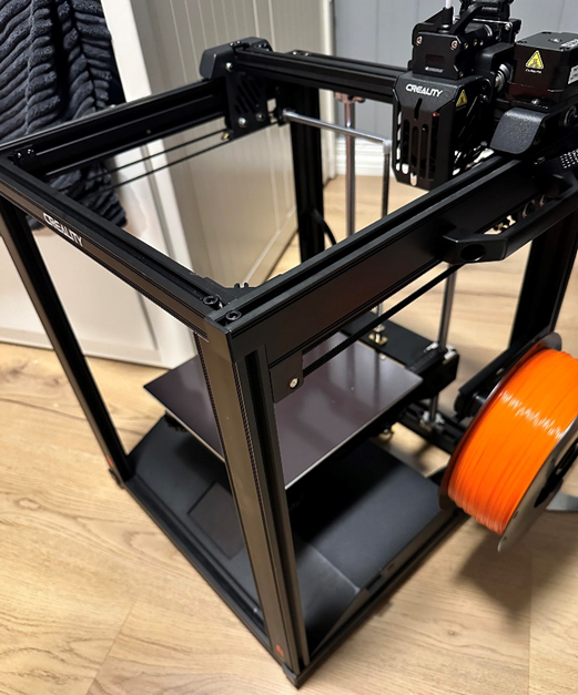
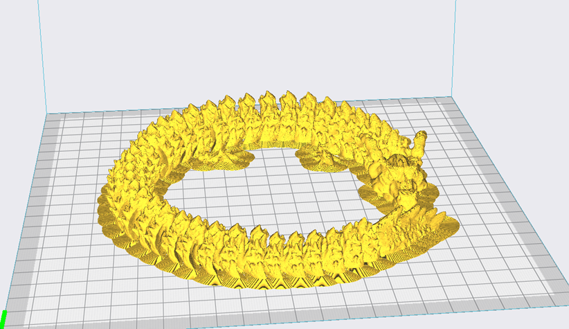
Before printing, I had to calibrate the printer. First, I manually calibrated the offset and leveling of the bed to give a ruffly 0.1mm space to the printer nozzle. This was done using standard A4 paper since the thickness is around 01mm. Then, after becoming happy with the calibration, I used the auto-calibration to do the finetuning. After this, I wanted to test the printer’s capabilities by printing something difficult. So, I used the following. https://www.thingiverse.com/thing:6233872
Since it was a difficult print, I set the layer height to 0.1mm and the infill to 20% to make sure I toggled adhesion to make sure no movement during printing.
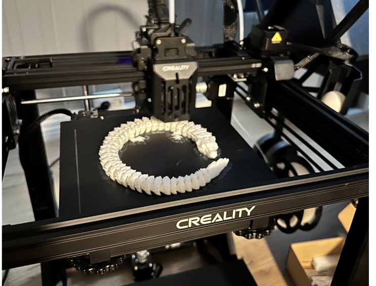
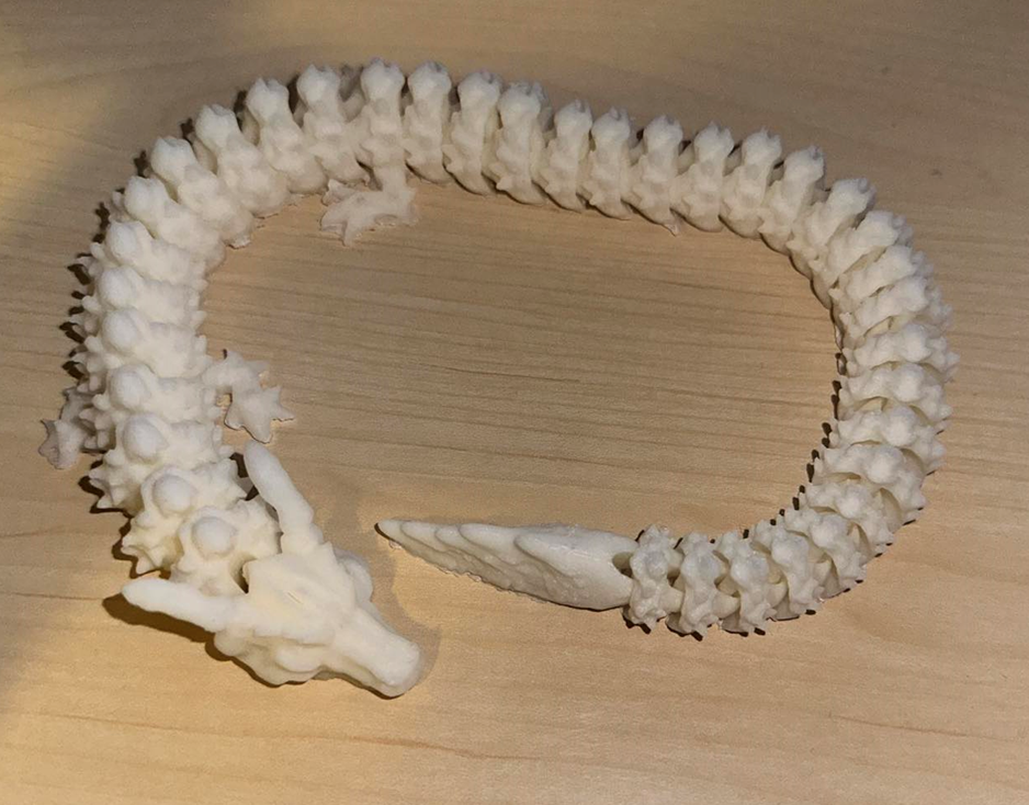
The rest of the week was used to test the 3D printer further with other types of prints.
Next week
For next week I hope to get all the components and construct the 5-volt regulator. Also, I plan to learn Fusion 360 and make a box for the 5-volt regulator, both for mitigating electromagnetic interference (EMI) to the rest of the system. since the step-down regulator being used can create a lot of noise.
Hannes Weigel
This week was used to review the remaining mechanical necessities of the system, and design adjustments
The Sun Gear Bearing
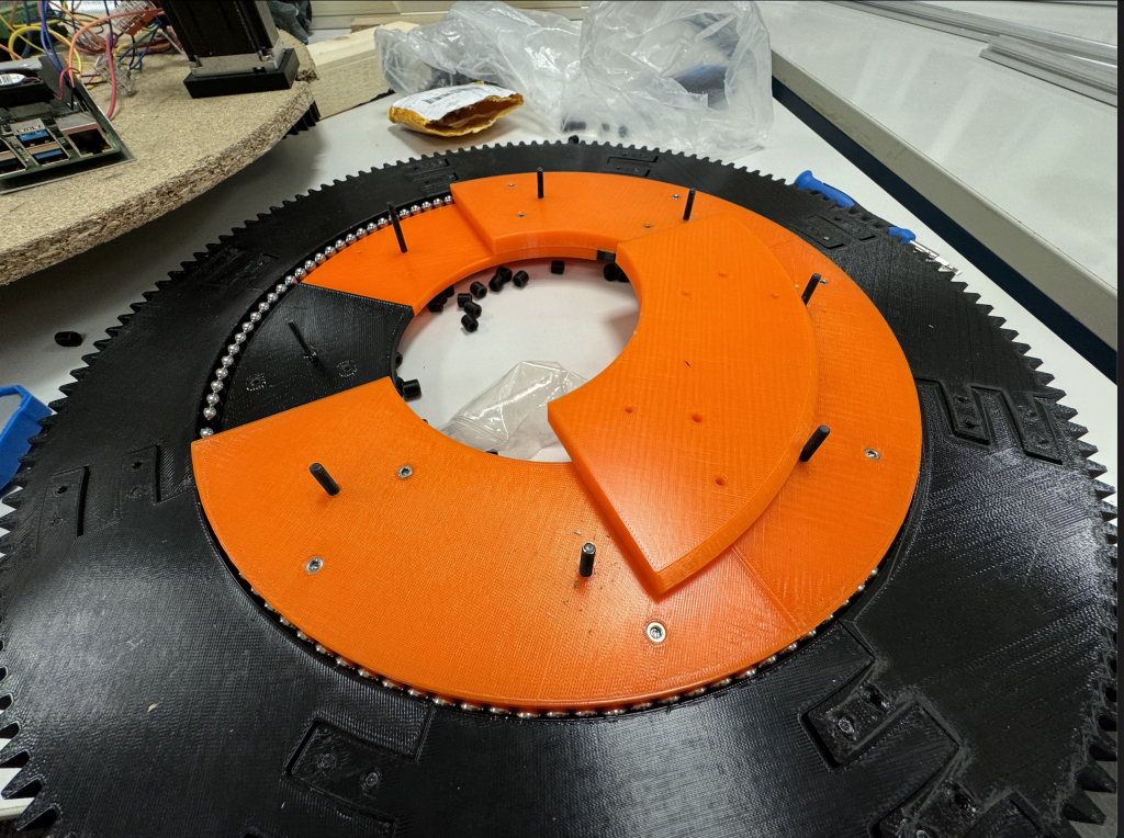
A month ago I had ordered 8mm bearing balls to replace the 8mm cylindrical rollers that were used in the bearing of the sun gear.
With the new bearing balls in place, the bearing ran a lot smoother with no hiccups during rotation.
Wiring
Additionally, I revised the cable routing of the 4 steppers with each their corresponding motor controller.
Further Work
The entire system has to be mounted on a portable surface, for example a pallet.
There are some more components that need to be mounted, but the mounting is not critical to operations.
To be able to shoot the desired type of projectile, we would preferably have a barrel with a uniform outer diameter (OD), as opposed to the variable OD barrel that we have now.
The projectile needs to be designed, as well as a testing environment for the entire system.