Andreas
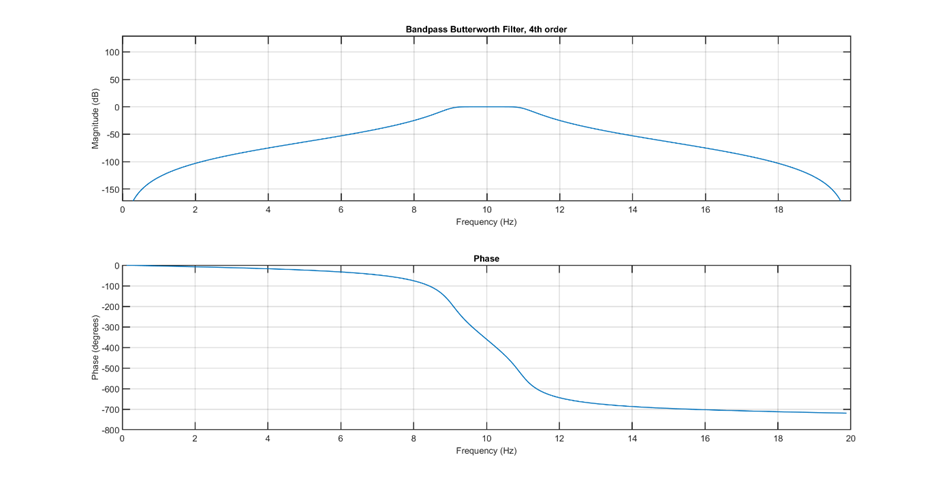
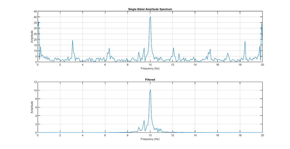
Thanks to the mindboggling revelations we could pulse the LED and then perform digital signal processing instead of analogue filtering. When considering the formfactor of the system we decided that we would either have to design a PCB to fit all the components into the size we wanted, or would have to filter digitally. This is why we decided to filter with digital signal processing. For this, you could use a lot of different types of filters, though one of the easier one to implement into code would be a Butterworth filter. For this, I have shown the responses below, as well as the frequency spectra of samples taken in Dronesonen, before and after filtering.
As well as filtering the IR sensor we have decided to increase the precision of our movement by using rotary encoders. As there are multiple ways of counting rotations, for the simplicity of implementation we decided to go with an optical rotary encoder. This encoder works the same way our IR distance sensors, though instead of measuring the reflected light, we measure if the sensor is blocked. This way we can make a disk that spins with the rotation of the axel with holes at specific angles so that we only need to count how many times we can see the LED. This can be used to measure distance travelled, acceleration or speed. In combination with the IR sensors, these will make extremely precise movement possible.
Firstly, purchasing the components for this was considered, though this would be an expensive purchase. Therefore, we decided to make one of our own with cheaper components. This would most likely decrease the precision we could achieve.
Bendik
This week i worked with Andreas on filtering the IR signal, pulsing it as he wrote to and using algorithms to attempt to filter out all other signals. We set the IR LED to pulse at a frequency of 10 Hz, and our sample rate was 40 Hz. I found a program that can read the IR receiver values from the serial port, and save them into a text file, which we then can import into Excel and make a line chart of the measurements.
After taking a couple hundred measurements in a room with minimal other noise, we got this graph:
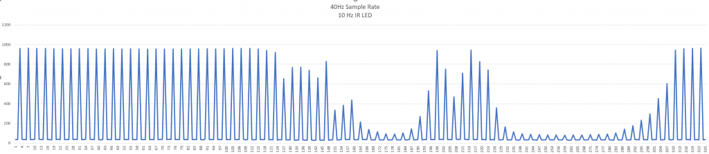
As you can see, the LED is pulsing with 10 Hz, and it is a very clean signal. Then we moved ourselves down the the Dronesone, which is a very noisy environment. This is what the graph looked like then:
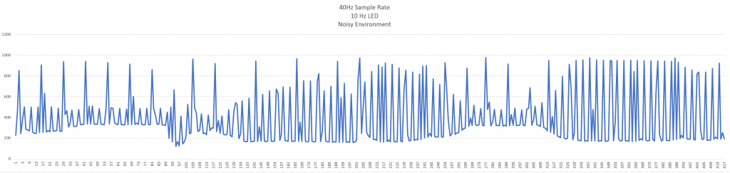
Now we were getting lots of unwanted signals that needed to be filtered out. I implemented the low-pass and high-pass filter that Jan-Dyre showed us in class, which made the signal quite a bit cleaner, but there was still noise in the signal. I am looking into implementing a band-pass filter to further clean the signal, only getting the pulses from the IR LED.
Marte
The second version of the MVP is ready, and the team is preparing for the drag race in week 43(10).
This week I have focused on making the MVP smaller with the goal to make it fit the maze better. In the drag race it is optional to make a turn or reverse back when the micro mouse reaches the wall to return back to the starting point.
We are aiming for getting the micro mouse to make a turn, but the final decision will be made when we know which alternative will be more time saving.
The first version of the MVP is too big to make a turn because of its length, so to reduce the length I designed an MVP that contains components on two levels.
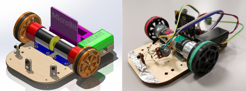
Dimensions 1st version:
Length: 150mm
Width: 137.5mm
Height: 58mm
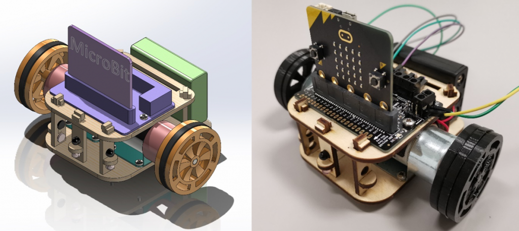
Dimensions 2nd version:
Length: 91mm
Width: 137.5mm
Height: 89mm
Reduction in length: 59mm
Increace in height: 31mm
These dimensions allows the MVP to make a turn in the maze.
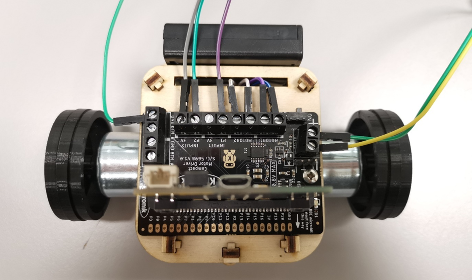
Axially positioned motors gives minimum width of 137.5mm (current width). With this width there is only 30.5 mm clearance to the maze walls. We would like to have a bigger clearance by reducing the width of the MVP.
Possible ways to reduce the width of the MVP:
- Change position of motors; place non-axially, parallel or perpendicular of current position
- Remove the gear box at the end of the motor
- Switch to smaller motors
We will first try to remove both the gear boxes which will reduce the width by 2x18mm reducing in a total width of approximately 100mm. This would give us 68mm clearance to the side walls in the maze.
In the upcoming week I will focus on improving the wheel’s grip and stability, since the 3D printed TPU gave less friction than expected.
Vendel
Given that the issues for the upcoming drag race seems to be going smoothly with the rest of the team, I have been content with just contributing to brainstorming sessions for the collaborative parts, while focusing on my own on what comes after.
After the drag race, there will be more reason to focus on the map aspect of the challenge. I have previously, before we took as much time off as we could defend last week, made an algorithm that can fill a map grid with values for closeness to the center, that should scale well. What I have been fiddling with since, is making the mouse know that it exists. I have broken the code, fixed it, broken it again, fixed it again, and discovered bugs, but finally, the brain has some spatial awareness. It can now track where it is, and what cells are around it. The hope is that making it turn around to face a direction, and then going there, should be easy enough.
Oh, and the virtual maze still doesn’t have any walls. That is one big TODO in the code of course.
The algorithm work is still in python as opposed to Ada, but my hope is that making the algorithm work in python, which is an easier language for me to code in and simulate at the moment, will make my work easier when trying to port it into Ada. While the rough algorithm is easy enough, the issue is figuring out exactly how to tell the code to do the right thing. Oh, and of course stitching this together with the currently existing work to make it look around and move. Funny how that also needs to be done. I might need to work a little late to get up to speed by the time we need to focus on integrating these things together.