Christopher Daffinrud
This week we used most of our Monday testing our system. We wanted to see our software and detection model working together with our hardware components making our turret rotate towards the detected object from our camera feed.
The communication between the input, the object detection and the output in controlling the stepper motors worked mainly fine, but there were several problems that we discovered:
- The resolution for the camera didn’t necessarily relate to the pixel coordinates output from the object detection-model.
- An issue where the system rotated the wrong way. When detecting an object to the right, it rotated towards the left. This should be a minor issue though.
Ole took upon him to look at the first issue, while I started to look into threading and parallel processes in Python.
We want our System to run efficiently, and we have seen that the detection model uses a lot of resources on the Pi resulting in low frames per second in output. Therefore I looked into multithreading in Python using shared_queue:
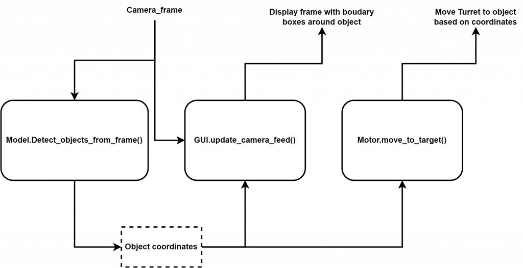
The diagram shows how we want three different objects using the same shared memory, either for writing (Model writes coordinates) or for reading (GUI and Motor reads from object coordinates).
With this structure we hopefully can make sure that the same frame passed to both the Model and the GUI ties to the same object coordinates written by the Model, Read by the GUI and read by the Motor.
The rest of the week I worked on implementing this communicative structure using Multiprocessing.Queue() and Multiprocessing.Semaphore(), but because of issues in installing the needed python Modules for the Detection Model, I may need to collaborate more closely with Ole to make sure it works with the Model we are using.
Next Week:
Hopefully, Ole and me can collaborate further to make this work and that we have solved the issue of resolution/coordinates from Model. From here we can really start to tie up the different components in our software.
Mats Bergum
This week I tried to get the rest of the parts needed to make the 5-volt regulator. However, due to sickness, me and Steven could not meet. Since I could not meet Steven, I tried talking to Zoran. He did, unfortunately, not have all the necessary parts. However, he gave me much advice and a much better solution. By using a Step-Down Switching Regulator(LT1074) instead, I would almost produce no heat compared to the old solution since the regulator has about 95% efficiency.
When using a Step-Down Switching Regulator, it is very important to have exact values on the components in the circuit. Especially the feedback (R1 and R2) and changes in any value will make an impact on the effectiveness of the regulator. So, to test the circuit before ordering parts, I changed the LTspice demo circuit provided by DigiKey to match the circuit I wanted to use and simulated the input and output.
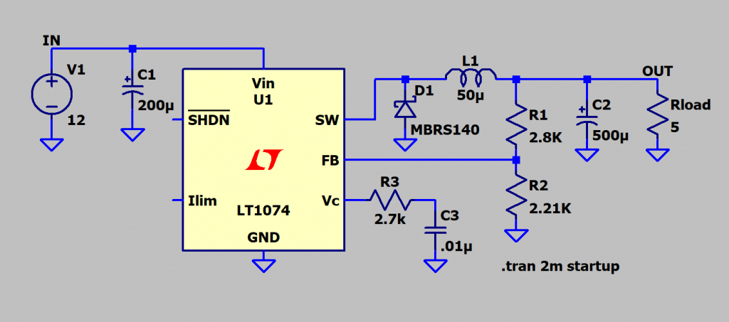
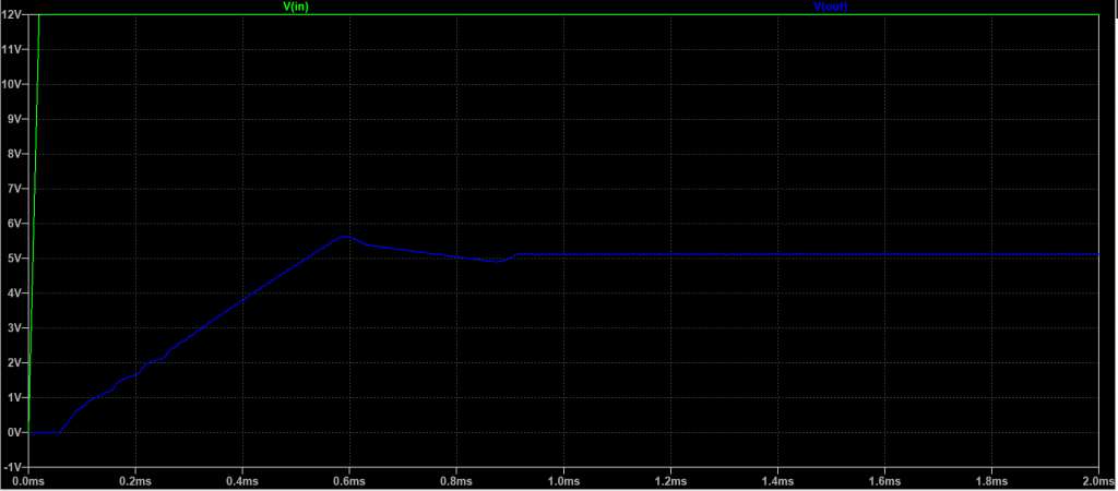
I was satisfied with the simulation and spent the rest of the week finding all the necessary parts on RS Components.
Next week, I hope to make the 5-volt regulator circuit on a stripboard. Of course, this all deepened on how quickly I can get all the necessary parts.
Hannes Weigel
The goal for this week was to complete integrating new components and start testing the system as a whole. The timeframe for this goal was short as fuck since Ole and I were flying to Portugal on Thursday to watch rocket launches.
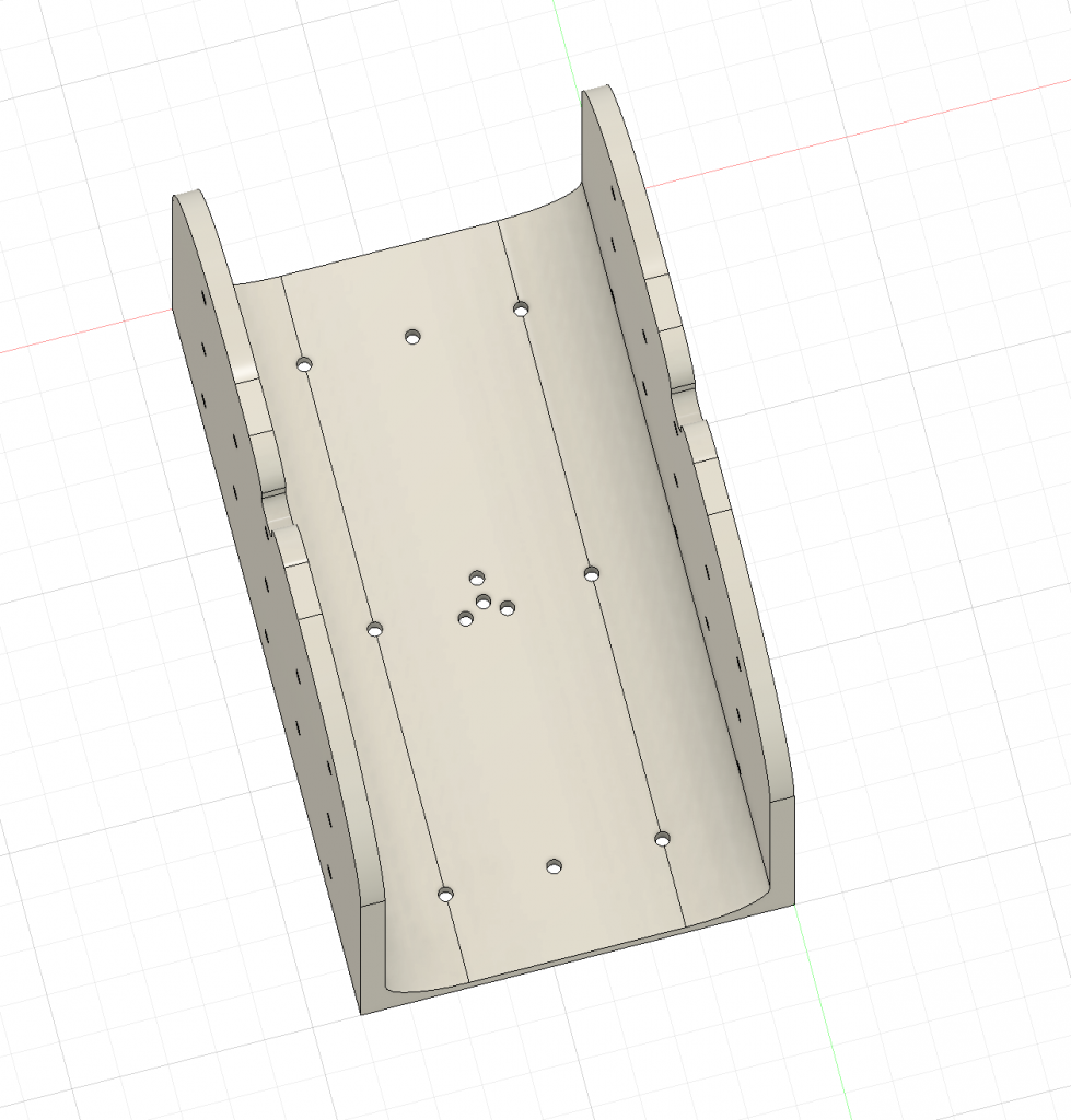
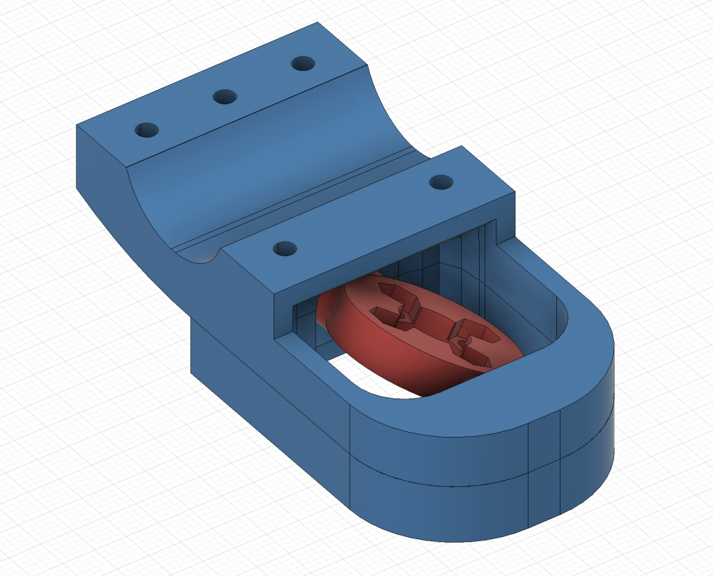
The Marker Holder
To hold the paintball marker and provide an axis for pivoting, we needed a frame to mount said marker on.
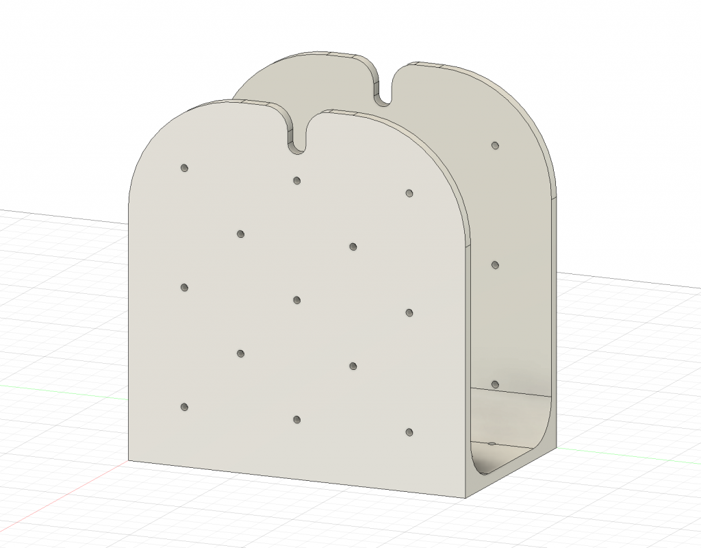
The frame features 26 lateral holes for M3 screws and a cutout at the top to hold a 6mm rod that would serve as the pivot point.
If this frame would not provide enough height, using the 26 holes, an extension plate could be mounted to heighten the pivot point.
The bracket would be screwed on to the mounting plate using an arrangement of screw holes I had previously drilled with a guide.
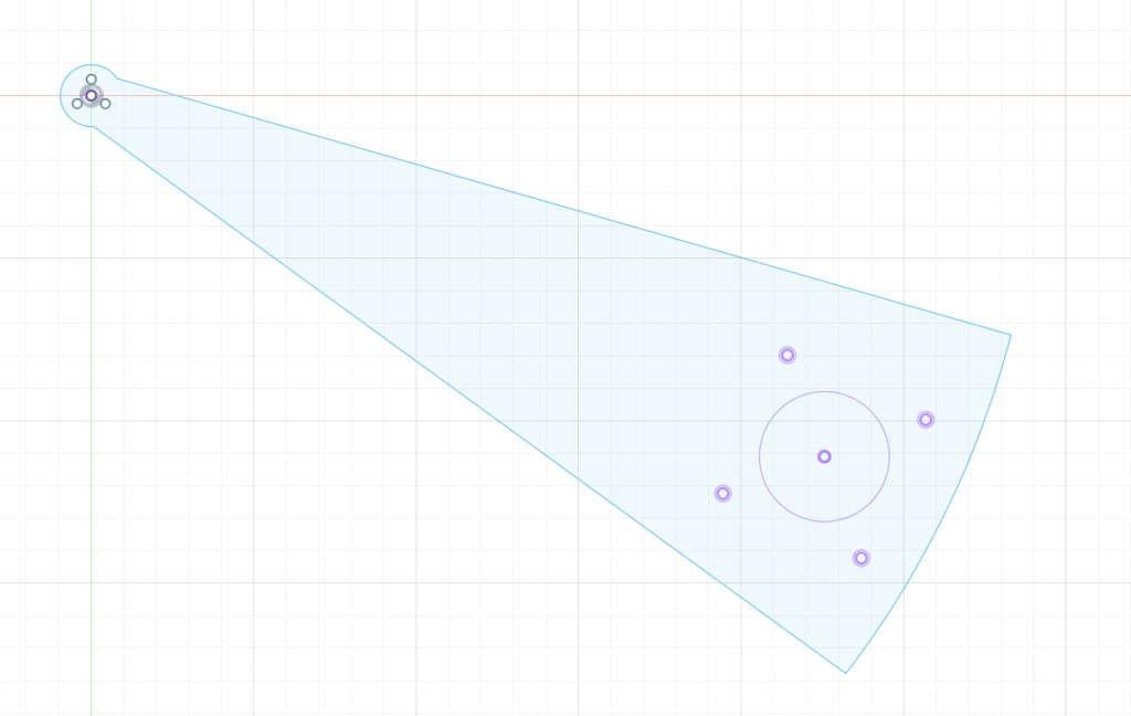
This guiding tool was cut in plywood for spacing out the motor mounting points on the mounting plate. In the top left you can see the characteristic 3 holes tangential to a central hole.
Once the marker was mounted in the bracket, the decision was made that the extension plates were needed for better clearance.
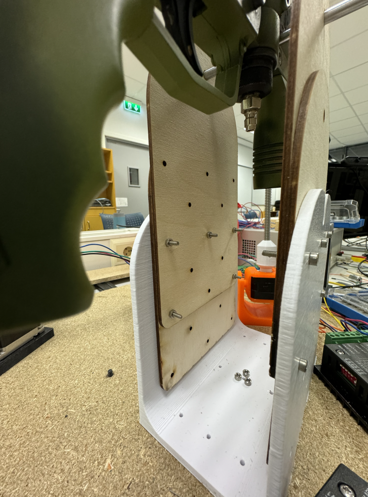
The Assembly
The pitch system was placed on the mounting plate, and the barrel clamp together with the holder for the nut was assembled.
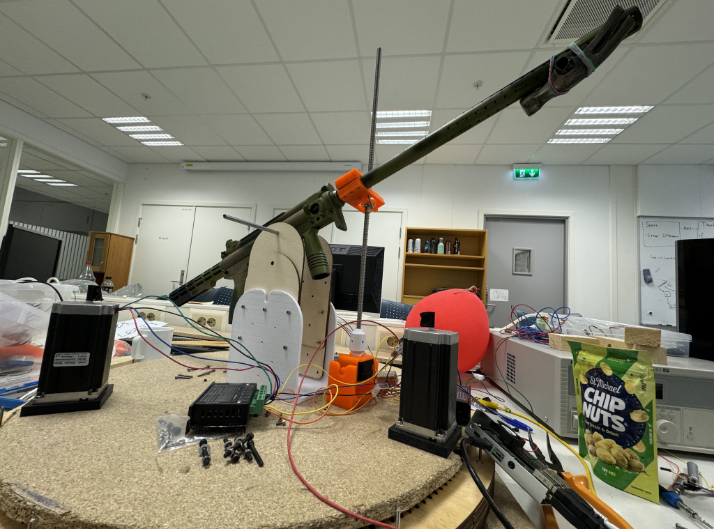
Since taking this picture, I have optimised the barrel clamp and the nut holder.
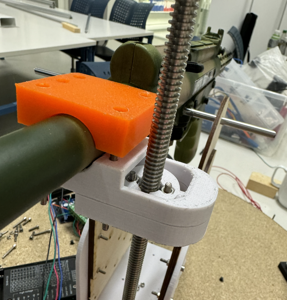
With this configuration, the rod is closer to the barrel and thus is more stable- given that we pitch off-axis of the tangential plane to the pivoting point.
Further Work
We need some holders and mounts for various items, such as the camera, and the pressure tank. Additionally a new barrel with a uniform outer radius and no relief holes is something I am aiming at manufacturing.
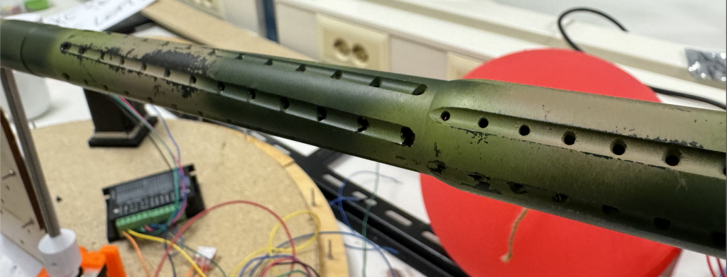
Aforementioned barrel and relief holes.
Rockets
Ole Eirik S.Seljordslia
This week was used to integrate and test parts of the system. We used the detection model to try and rotate the azimuth drive based on whether the balloon is placed on the left or right side of the camera. I spent some time merging our branches to create a homogenous branch where both the logic for the turret and the detection model exists.
I created an example to test parts of our system together, this integrated: the detection model, driving the moter, displaying the results. The essence of our test is captured in the following code block.
1 2 3 4 5 6 7 8 9 10 11 12 13 14 15 16 17 18 19 20 21 22 23 24 25 26 27 28 29 | while camera.isOpened(): result, image = camera.read() if not result: print(f"Unable to open camera{camera_id}") exit() image = cv2.flip(image, 1) rgb_image = cv2.cvtColor(image, cv2.COLOR_BGR2RGB) input_tensor = vision.TensorImage.create_from_array(rgb_image) detection_result = detector.detect(input_tensor) if len(detection_result.detections): detection = detection_result.detections[0] cv2.rectangle(image, (detection.bounding_box.origin_x, detection.bounding_box.origin_y), (detection.bounding_box.origin_x+detection.bounding_box.width, detection.bounding_box.origin_y+detection.bounding_box.height), (0,0,255), 3) cv2.imshow('Camera feed', image) object_x = detection_result.detections[0].bounding_box.origin_x + detection_result.detections[0].bounding_box.width) object_x = round(object_x) print(f"object_x: {object_x}") camera_center = camera.get(cv2.CAP_PROP_FRAME_WIDTH)/2 print(f"camcenter: {camera_center}") camera_center = round(camera_center) motor_driver.move_to_target(object_x, camera_center, 50) if cv2.waitKey(1) == 27: break camera.release() cv2.destroyAllWindows() |
First the camera is opened, then it’s flipped and converted from BGR to RGB. This is to conform with the models expected input. The image is then recreated as a tensor and needed to the object detection model.
Then if there are any detections we enter the logic for driving the motor. We only focused on the first detection to simplify the test instead of processing all detections. Since our model only detects balloons, we don’t need to check what the detection is.
Since only the azimuth drive is ready for testing, we only calculate the objects x-coordinate. This should determine whether the turret should turn left or right. The x-coordinate is calculated as the centerpoint between the models lowest left most point and the models lowest rightmost point.
The azimuth motor is then driven either to the right or the left on the x-coordinate’s position relative to the center of the camera(the camera is planned to be mounted in the same direction as the barrel).
This showed to be more problematic than we expected. Our turret would only turn in one direction. This problem will be explored more in the coming weeks.
More rockets
Harald Berzinis
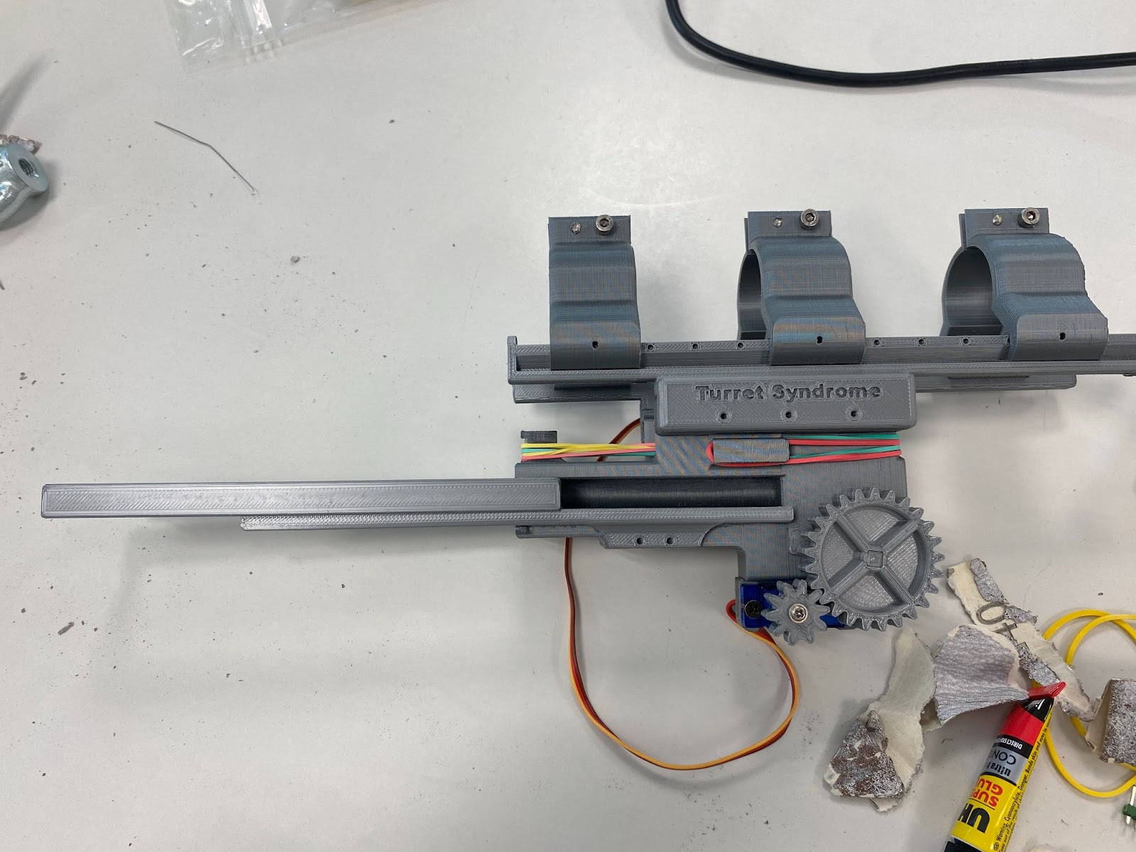
This week I have been 3D-printing the trigger mechanism and the results are promising!
The Printing Process
I used PrusaSlicer to slice the different parts. I set my layer height to 0.15mm, using only PLA filament and quality mode setting on my MK3s to ensure that the holes, bolts, gears and other moving parts would be precise enough for the use case. The infill for each component differed from 30% to 70% ranging from what type of part it was, and how sturdy it should be in its context.
The printing went as expected where there were no problems occurring. The printing process took around 45 hours to completely print the entire mechanism.
Assembly
The assembly went as planned, and all of the parts fit together, but some areas where the main bolt was moving through the body I needed to do some sanding with some P250 sandpaper. In addition, the assembly was done with superglue. Furthermore, I used some M2 bolts to secure the mounting parting for the buttstock, and some screws to fix the servo in its place and the 10 teeth spur gear with the servo.
Testing
Here are some pictures showcasing the trigger mechanism in a unloaded and loaded state:

Here are two small videos that showcase the mechanism working manually, where I turn the servo gear to initialize the mechanism:
As you can see here, the trigger mechanism is working and it is engaging the paintball gun’s trigger. While testing, two rubber bands were not sufficient enough to drive the trigger due to the air pressure of the gun, so I needed to add two more in order for the mechanism to work properly. Regarding the mechanism itself, the servo could withstand the rubber bands force towards the lever, and it would not move when it was not supposed to do which is a good thing, and it is working as expected.
Next week
I have received some parts including a small breadboard, some headers, and a button which acts as a switch. Next week I will be using these components to make the servo turn the lever to the loading position after a press of the button. When the button is not pressed the mechanism will be in a loaded state and ready to fire again. Another thing I will need to do is make the mechanism mounted more securely to the butt stock with rubber padding or some other material.