Hi Dronesonen! 😊
This week we have conducted the following efforts:
Discipline – Software:
Erik-Andre Hegna:
This week was spent on researching/discussing how the micromouse will know and keep track of its position inside the maze. We want it to understand that it is moving from a 16×16 cm cell and into another 16×16 cm cell. After talks with Steven, we figured that each cell will have a 1,2 cm long geometrical structure which divides each cell. We want our sensors to notice this difference, but we need alot more calibration and timing to be able to do that with IR-sensors at the moment.
We also tried out a ultra-sonic sensor. This sensor had much better range than the IR-sensor. So maybe a mix of both (ultrasonic in front, and IR-sensors at the side) can be a good idea. We also started making python code to visualize the data sent from the sensors over the USB-port.
Lars Leganger:
This week I started to look at the remaining software challenges ahead of us. I did some research on different ways for the micromouse to map the maze. I researched the maze to get some clarity on what is in it for the mouse to detect. We also looked at different solutions for its detection to try to figure out what sensors we need and if they can do what we want them to do.
Ask Lindbråten:
The goal for this week was to receive and handle measurements from within the maze, aswell as plotting and potentially adjust these measures for further usage. Earlier this week Hugo spoked to me about opting to use ultrasonic sensors as an alternative to the IR-sensors, since they have a lot less noise. So, I began the session on Wednesday by writing a script that could print the distance (in cm) to “obstacles” or walls in the maze. The script below works as follows:
- Setting the trigger-pin to LOW and delaying for 2 microseconds to ensure that the trigger signal settles before proceeding.
- Setting the trigger-pin to HIGH and delaying it for 10 microseconds to ensure that the sensor generates a stable pulse, before setting it to LOW.
- Setting the duration variable to the time (in microseconds) for the echo-pin to go from LOW to HIGH. In simpler terms, the echo-pin is LOW when the ultrasonic sound is emitted and goes HIGH when the sound encounters an object and bounces back to the sensor. The pulseIn()- function returns the time of this process.
- The pre-adjusted distance value is then calculated using the duration in microseconds multiplied with the speed of sound in cm per microseconds [cm/microseconds] divided by 2, since we only want the distance from sensor (A) to the obstacle (B) (Not A->B->A).
- The results are printed to the screen.
#include <Arduino.h>
#include <cmath>

// put function declarations here:
int echo_pin = 1;
int trigger_pin = PIN_BUTTON_A;
float speed_of_sound = 0.0343; //cm per microsecond [cm/microsec]
float duration;
float pre_distance;

void setup() {
  // put your setup code here, to run once:
 pinMode(trigger_pin, OUTPUT);
 pinMode(echo_pin, INPUT);
 Serial.begin(115200);
}

void loop() {
  digitalWrite(trigger_pin, LOW);
  delayMicroseconds(2);

  digitalWrite(trigger_pin, HIGH);
  delayMicroseconds(10);
  digitalWrite(trigger_pin, LOW);

  duration = pulseIn(echo_pin, HIGH);
  pre_distance = duration*speed_of_sound/2;

  Serial.print("The distance is: ");
  Serial.println(pre_distance);
  delay(1000);
}
After running this script with an ultrasonic sensor in an open rectangular box with a max-length of 50 cm and an adjustable end wall, we quickly noticed that the sensor had a large error margin of -13 -> -8 to obstacles at a distance of (30, 40 and 50) cm from the sensor. In other words, when the real word (RW) distances would be x, our printed distance value would be x – (8 -> 13) of the RW values: (30, 40 & 50) cm. When RW = 10 however our printed values had a much smaller error margin of -3 -> +1.
To verify and substantiate our initial hypothesis, we wanted to plot a lot more measurements in Spyder using the matplotlib library. To do this, I decided to create and write to two text files: one for the distance values and the other for the time it was calculated. Seems simple enough right… or so I thought. I first tried using the “fstream” library with the necessary logic, but VSC reported errors from within the library. Then I tried using the “FS.h” – library, with the SPI Flash File System, but I came to the realization, after a bit of googling, that the values would be stored to the flash memory of the microcontroller, so I discarded that idea.
Next up, I tried using the libraries: “cstdio” and “cstdlib”, with the necessary logic but that didn’t work either. At this point, it seemed the only viable option would be to use python logic, but since I didn’t have access to the Microbit and the week was approaching its latter end, I made the decision to leave the troubleshooting for now and make a quick function that could adjust the distance values to the corresponding real word values based on the insights we had gained prior to my decision to start the plotting process.
I wrote the following code in Visual Studio to adjust some example measures to the error-margins we discovered, keep in mind that this script doesn’t account for the specific measurements where measurement (n) modulo 10 != 0, and n is not included in the if-conditions. To adjust for those measurements, we would need to do some more testing.
#include <iostream>
#include <vector>
int low_lim = 10;
int mid_lim_1 = 20;
int mid_lim_2 = 30;
int upper_lim = 40;
int measurments = 15;
int adjDistToRW(int n);
int main()
{
std::vector<int> pre_adj_dist_vals{11,10,17,18,19,21,37,38,39,41,40,7,8,9, 28,29,31 };
std::vector<int> adj_dist_vals{};
for (auto x : pre_adj_dist_vals) {
adj_dist_vals.push_back(adjDistToRW(x));
}
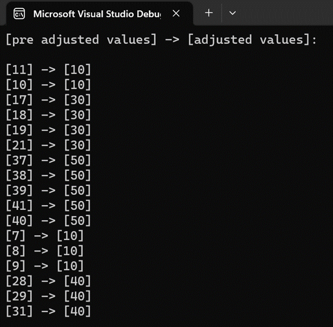
std::cout << "[pre adjusted values] -> [adjusted values]:\n\n";
for (int i{ 0 }; i < pre_adj_dist_vals.size(); i++) {
std::cout << "[" << pre_adj_dist_vals[i] << "]" << " -> [" << adj_dist_vals[i] << "]\n";
}
}
int adjDistToRW(int n) {
if (n <= low_lim + 1 && n >= low_lim - 3) {
return low_lim;
}
else if (n <= mid_lim_1 + 2 && n >= mid_lim_1 - 3) {
return mid_lim_2;
}
else if (n <= mid_lim_2 + 2 && n >= mid_lim_2 - 3) {
return upper_lim;
}
else if (n <= upper_lim + 2 && n >= upper_lim - 3) {
return upper_lim + 10;
}
else {
return n;
}
}
Running the script gave the following results:
Discipline – Electrical:
Hugo Valery Mathis Masson-Benoit:
The week was full of change and improvements for the project, most of the hardware has been replaced.
Sensor part:
Due to the noise and the poor signal we had with the IR sensor, I wanted to try ultrasonic sensor to replace them. I got some HC-SR04 from our teacher and began my research to implement them. There are way easier to work with and directly give the distance in centimeter between the sensor and the wall in front, making it easy to know where the walls are up to 4 meters. After implementing it, here’s the result:
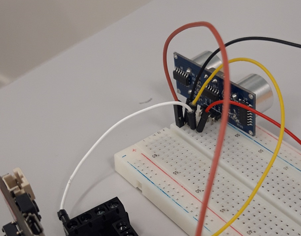
They don’t need any other component to work with, only the MCU. The input and the output are directly managed by the Microbit, and sensor need to be supplied with 5 volts. To do this, we’re going to replace or voltage regulator 9 volts to 3 volts, for 9 volts to 5 volts to supply the ultrasonic sensors. The result is pretty accurate, even if there are still some adjustments to do on the software side.
Motor part:
The original motors we were given were very big. It made it difficult to move and mostly turn in the maze. So, I asked for some smaller motors to try. I was given two Pololu motors of 30.1 ratio and a supply capacity between 5 volts and 12 volts. Even if there are slower than the original, their size are a big plus to help reduce the size of the Micromouse. Here you can see the size difference between the two motors:
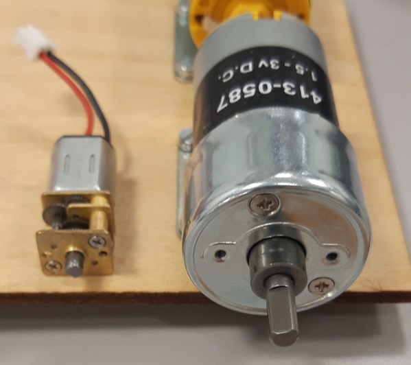
Due to the internal voltage regulator of the Microbit board, we can directly connect the 9 volts battery to the board. This way the motors are directly supplied with 9 volts and still controlled by the Microbit, giving us a good rmp in the end. We still need to make a wheel for it, and verify the power consumption of this design, but it’s encouraging.
Encoders:
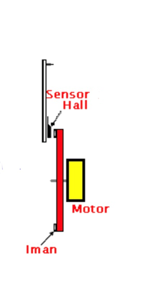
To know where the Micromouse is in the maze, we need to put some encoders on the wheels to know its position. To do so we have multiple choice, and we decided to go for some magnetic encoders, by putting some small magnet on the wheel and placing a magnetoresistive sensor just next to it, telling us how much the wheels are moving (the accuracy depend on the number of magnet). This way we won’t have any noise coming from the ambient light, and the sensor will be far enough from the motor to not have any impact on it. The goal is to have something looking like this:
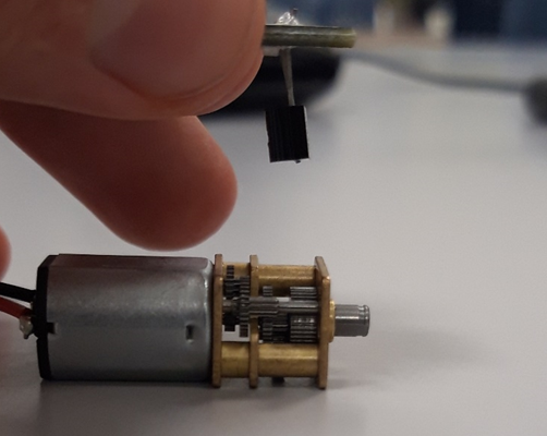
(With the magnet on the edge of the inner face of the wheel, far enough from the motor.)
The perfect component for this would be the SM315RT, a transistor like component able to do the job. I need to ask our teacher about it to know if we have a similar component at the university, or if we need to command it. Concerning the magnets on the wheels, it’s up to the mechanical part to design it.
Conclusion:
The hardware of the Micromouse has been entirely changed this week, with new sensor and motors. The last needing to be implemented are the encoders.
Objective for next week:
Start the design of the encoders.
Jemima Niquen Tapia:
As the MVP is pretty okay, this week hasn’t been really practical, so this week I have been doing more research. My partner told me that electronical part needs some change. Also, I talked with the teacher about do some encoders with light sensors, and we were planning how to do it with the mechanical part, but finally we change, and we’ll do the encoders with the magnetic sensor. So doing some research the principal idea of the encoder is the one we see in the picture. Then now we have to know how to do the circuit for the sensor, also see how to adapt it with the other components. A good option to do it could be to use the hall sensor (A1104) because it’s a really easy xip to use; it has only 3 pins and also a Schmitt trigger, that helps with conditionate of the output of the sign.
Discipline – Mechanical:
Cesia Niquen Tapia:
This week I couldn´t do much. I´ve been thinking for a better and improved design of the wheels .Smaller, thinner and with more traction. As when we put it in the maze and as we expected , it was way too big to maneuver. As a conclusion and talking with Richard the best way is to create and print a rubber band with flexible filament. This way we can use the size that fits better to the smaller design.
This concludes our blog post for week 7, see you next week!😊