Christopher Daffinrud
This week my main area of work was primarily focused around two tasks.
Turret Rotation Towards Detected Object:
The first task is the connection and calculation between the Stepper Motors used for rotation and the camera used for object detection. Based on our model for detecting objects we can extract the coordinates for the bottom left corner and the top right corner.
Our web-camera (Sandberg 1080p) has an Field of View (FOV) of 80 degrees in 1080p resolution. With that information and other relevant variables from the Stepper Motors and Stepper Controllers we were able to calculate the number of steps needed for rotating towards an object based on pixel-coordinates:
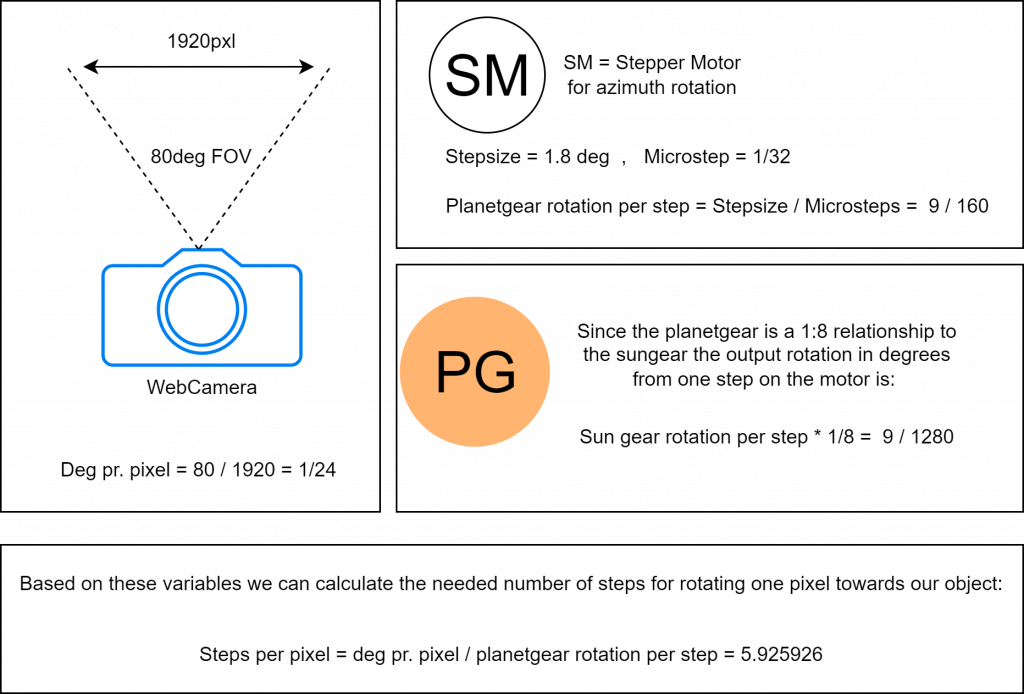
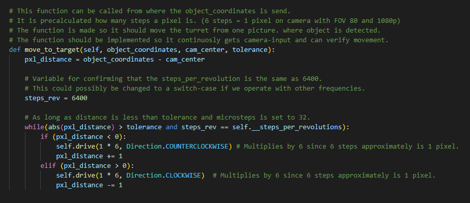
The Stepper Motor only accepts steps in integer-values so for testing purposes we will try using 6 steps per pixel.
I also created a function in our Motor-class which hopefully for testing will be able to rotate the turret to our detected object or in close enough proximity to be able to adjust some sensitivity-settings.
Turret Simulator In Unity
My other focus task this week was to try to create and simulation for our Turret System in Unity with functionalities such as auto-aiming towards red objects and preventing the system to aim or fire when a green object is within sights. Here is a video showing the simulator in action:
The code for the Simulator is mainly from four scripts:
- BalloonSpawner – Spawns Red and Green balloon-objects at the desired range and rotation.
- TurretRotator – Rotates the Turret itself between -90 and 90 degrees.
- GunElevator – Rotates and Elevates the gun between the Azimuth of -90 to 90 degrees and the pitch between 0 – 30 degrees.
- GunShooter – Instanciates a Bullet-object and its velocity and trajectory based on where the Muzzle is pointing towards.
There is also implemented an Input System which maps different Keys to different actions when running the simulator.
The Gun-asset and the gear-system itself are only placeholders for hopefully imported CAD-files that represent those parts of our system.
Work for next week:
Turret Rotation Towards Object:
A better way of implementing a function that turns the turret towards the object would be a function that gets called for every camera-frame an object is detected in or at least for every few frames instead of the first one. The function above is mainly for testing purposes that our calculations and presumptions around the motors and controllers are correct and is not a safe way to implement this functionality.
Turret Simulator:
There are several other functionalities I will add to the simulator:
- Spawning objects within a reachable altitude for our turret.
- Insert the same values as the Stepper Motors we have ourself. Making it easier to visually get a sense of how fast our turret turns based on different frequencies and microstep-adjustments.
- Adding CAD-designs for our Gear-system and our Gun.
Hannes Weigel
The goal for this week was to implement the pitch rotation such that the paintball marker can be elevated, and additionally finish the last pieces of the azimuth drive system.
The Pitch Drive
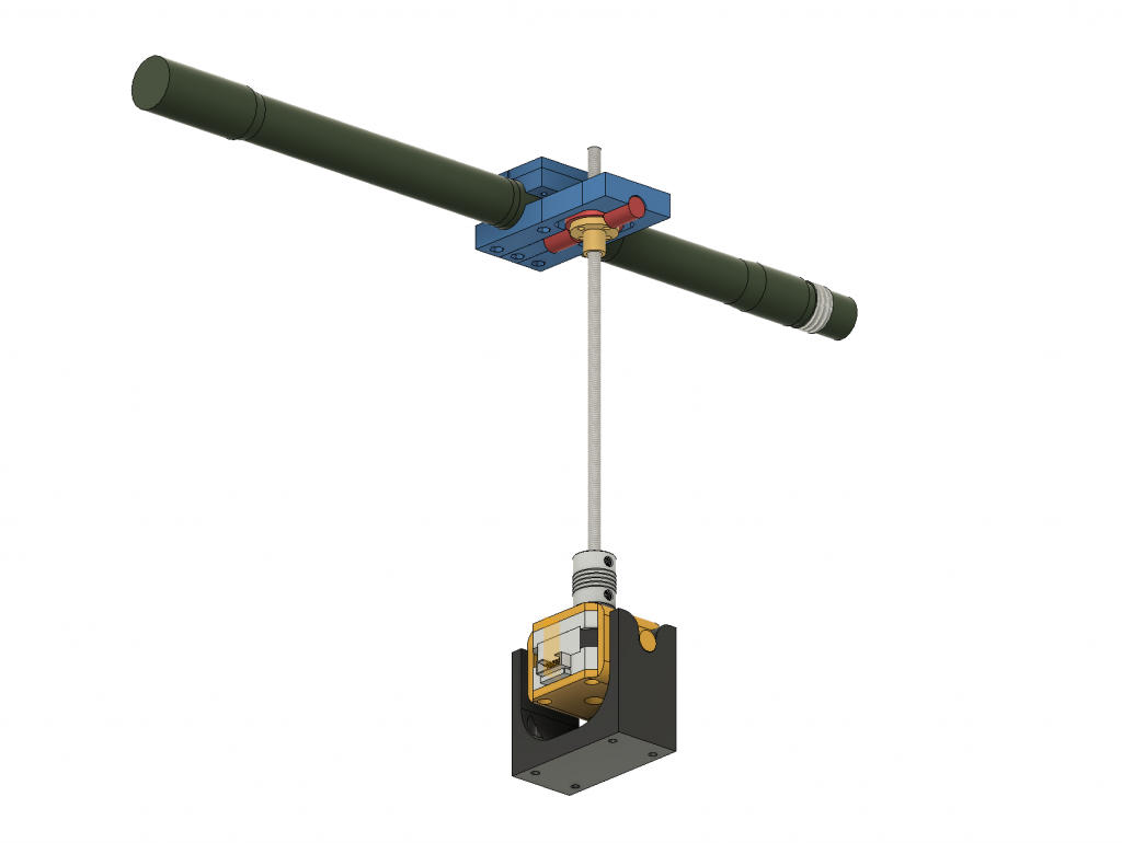
The pitch drive functions via a stepper motor that turns a trapezoidal threaded rod which in turn screws a nut (in gold) upwards or downwards.
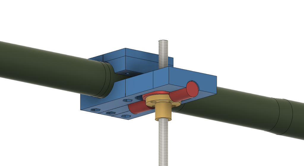
The nut is bolted to a plate with pinions on each side that allow the assemble 1 rotational dimension of freedom.
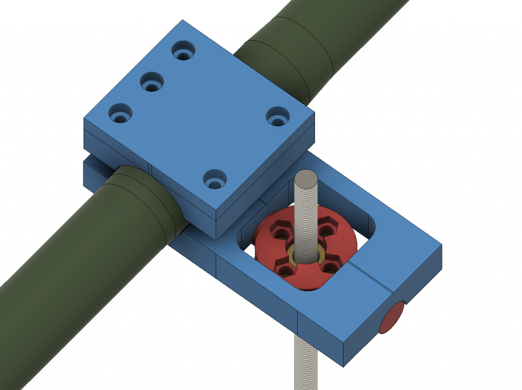
To hold this assembly to the barrel, the barrel is clamped together.
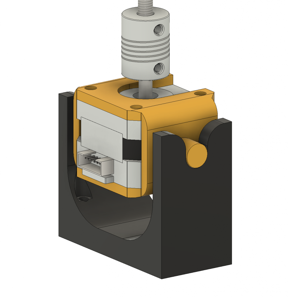
The motor is held by a “cradle” with pinions on each side that give it 1 rotational dimension of freedom. The pinions slot into the mount that directly bolts on the rotating base plate of the turret system.
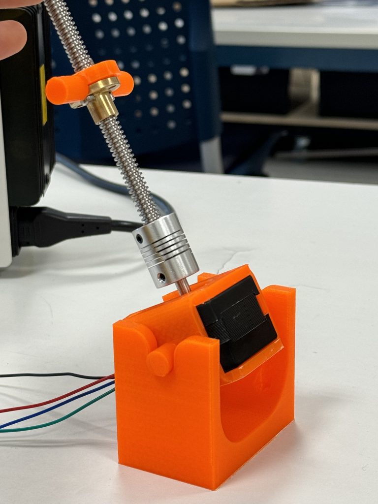
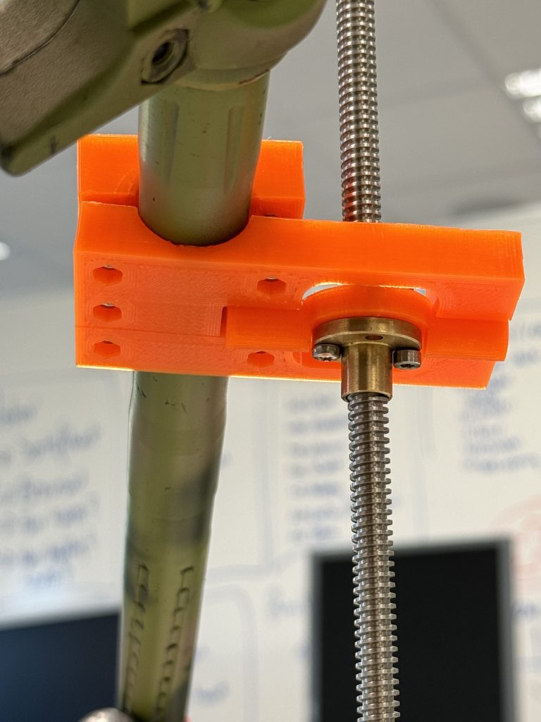
Disregard the barrel clamp being screwed on askew, and the two different kind of bolts on the nut carrier.
The Azimuth Drive
We have rotation 😎
Initially we had problems with all three motors turning at the same time. After relentless troubleshooting, we discovered the problem to be that we used one motor controller for all three motors. Meaning; If one motor lagged behind, it would forcefully be turned by the other motors, and due to the nature of the design, provide a current to the motor controller.
Basically; Two motors turn one motor which produces a current that interferes with the signal.
Further Work
As the azimuth and pitch drive mechanism are finished, the complete locomotion system is done. The goal for next week is to complete the integration and start testing the whole turret.
Ole Eirik S.Seljordslia
This week’s focus has been on trying a new model architecture. I wanted to try a more lightweight model than efficientdet. EdgeImpulse’s Faster Objects More Objects(FOMO) model seemed like a promising option, some examples were achieving upwards to 60 fps when doing object detection. FOMO is designed to be run on microcontrollers, where computational power is low.
Creating the model and training it was quite straightforward and can be described in the following steps:
- Transformed metadata to conform to EdgeImpulse’s format
- Set model architecture
- Set hyperparameters
- Train model
I started by converting the metadata for the dataset, the following code snippet transforms our datasets metadata from CSV to EdgeImpulse’s JSON format.
1 2 3 4 5 6 7 8 9 10 11 12 13 14 15 16 17 18 19 20 21 22 23 24 25 26 27 28 29 30 31 32 33 | import pandas as pd import ast import json df = pd.read_csv(r'dataset/balloon-data.csv') output = { "version": 1, "type": "bounding-box-labels", "boundingBoxes": {} } df['bbox'] = df['bbox'].apply(ast.literal_eval) for index, row in df.iterrows(): bounding = [] for box in row['bbox']: bounding.append({'label': 'balloon', 'x': box['xmin'], 'y': box['ymin'], 'width': box['xmax'] - box['xmin'], 'height': box['ymax'] - box['ymin']}) output['boundingBoxes'][f"{row['fname']}"] = bounding with open('dataset/bounding_boxes.labels', 'w') as f: json.dump(output, f) |

I tried to train the model using different architectures and hyperparameters. Training happens in EdgeImuplse’s cloud solutions, so when I wanted to increase the number of epochs(a full pass of the dataset) and ran the model, it would crash/timeout because the batch job took too long a time. This was quite frustrating as I would not be able to adjust parameters without paying for a subscription. So I tried creating models using FOMO and MobileNetV2, with limited epoch’s. But this did not yield any promising results, when validating the model’s accuracy; they would score with around 40%. I tried running inference on these models with the raspberry pi. The result was a very quick model that wrongfully identified items as balloons, which is not ideal when we plan on shooting those “balloons”.
We have talked a bit back and forth this week about how we want to achieve movement towards a setpoint with our turret. Since our goal is to identify and shoot stationary balloons, we only really need one update on the location of the balloons. This means that we could in theory only take one picture to locate each balloon, then we could move our turret’s barrel towards the coordinate set by the locations. So I believe that achieving a high FPS is not critical for our operation. Averaging locations a few times per second could increase our precision and hopefully reduce the number of false positives.
We will discuss our solution for movement more next week and hopefully conclude on what requirements should bound the image processing.
Mats Bergum
This week, I have mainly focused on designing a battery solution for our system. Last week, I found that all motors for the horizontal rotation can use up to 3 A each. Of course, during testing, the total current draw was not over 2 A with a 24 V voltage supply, so I chose to use this as the rated current. Moreover, the Raspberry Pi is planned to power all control circuits. Thus, I only needed to think about the power consumption of the Raspberry Pi, and according to the datasheet, it uses 5 V with a max current of 3 A. Since we are putting a lot of strain on the microprocessor, I put the rated current to 3 A.
| Component | Voltages | Rated current |
| Stepper motor (23HS8430) | 24 V | 2 A |
| Stepper motor (17HS) | 24 V | 0.6 A |
| Raspberry Pi | 5 V | 3 A |
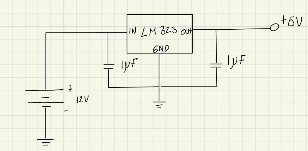
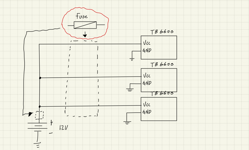
When I came to Steven with the requirements, he helped me find components that could meet these requirements. We found a 34 V battery made for an earlier Bachler project and a 5-volt regulator (LM323K). The regulator meets some of the requirements. The datasheet, see under, shows that the maximum output current ranged from 3 A to 4.5 A. However, the maximum input voltage was 20 V. This means that it can not be used with the 34 V battery Steven showed me. Moreover, the battery was too big and heavy to be mounted to the rest of the system in a good way.
From earlier testing on the system, I know that all the motors work fine with a supply voltage of 12 V. So I moved over to the idea of using a motorcycle battery because this is something I may have at home.
Simple schematics
Next week
Next week I plan to make the regulator circuit on a sodering board and test it with the rest of the system. I will of course also look for a usable 12 V battery.
Harald Berzinis
This week I have been designing the rest of the trigger mechanism, and it is now ready to print!
Initial CAD-design
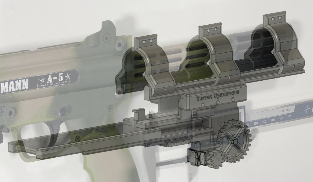
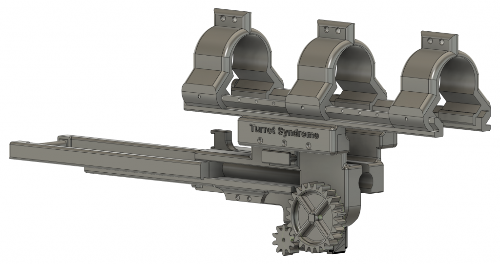
Here are some pictures from different angles of the entire contraption.
New Parts
Reworked main body to feature the new parts.
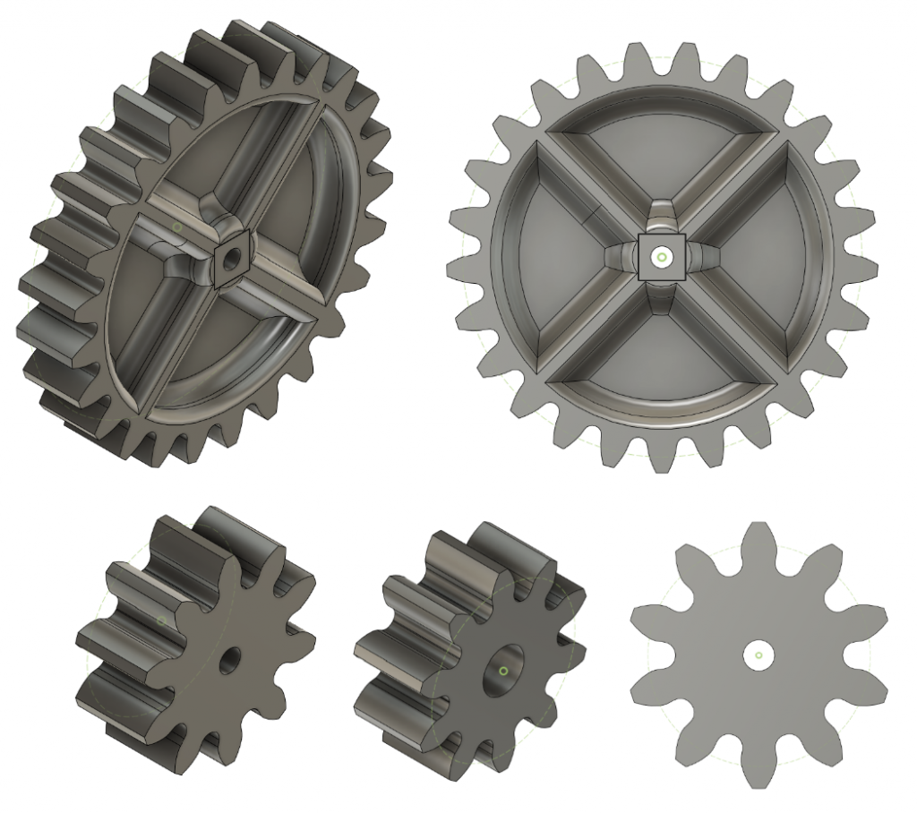
25 and 10 tooth gears.
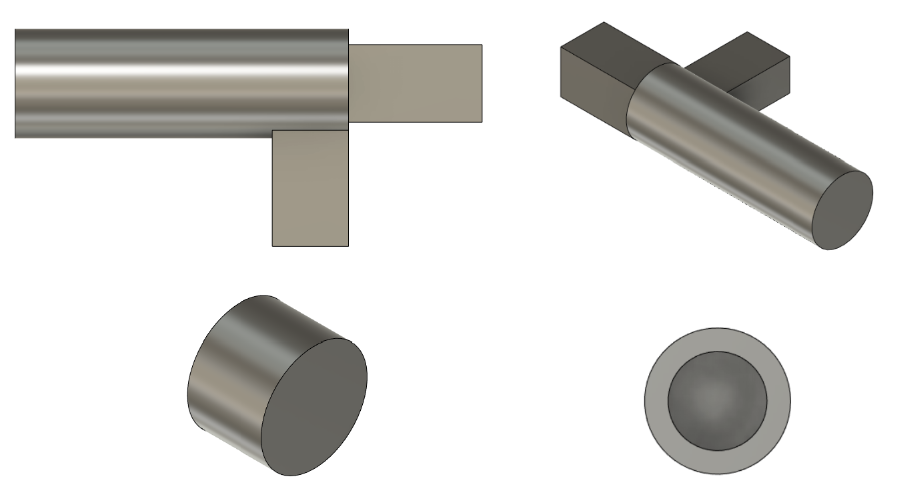
Holds the 25 tooth spur gear in place.
The parts above are for the new reworked servo mechanism which activates the main bolt. This time I have done a different approach where the bolt stopper is not directly connected to the 25 tooth gear, but rather leveraged in order to remove unwanted stress on the servo motor. This also makes the mechanism way more secure regarding safety, due to the trigger mechanism needing to be loaded twice in two separate locations.
Next Week
My plan for the next week is to 3D-print this concept, and initially test it with the paintball gun.