Andreas
This week has been slow-going as exam preparations for next week and other workloads have ensured little progress. This, combined with technical difficulties in the ECAD software has made both labs in other subjects and PCB design for this subject difficult.
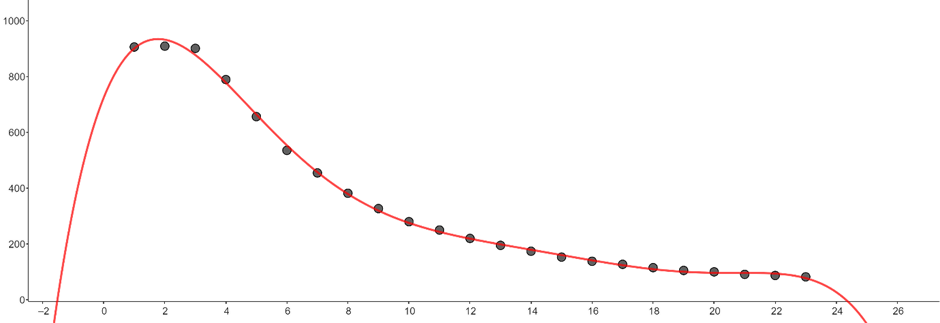
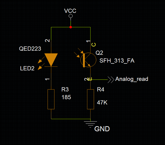
Despite this, we have calibrated the sensors, by limiting the LEDs so that they do not emit too much light. We have done this by limiting the current, ranging from 10 mA to 100 mA. By varying the distance, and plotting the voltage measured at the receiver, we found the expected inverse square function. This function varies by increasing or decreasing the amperage. We found a correlation by increasing the amperage we achieve higher sensitivity at further ranges, though lose it at lower, while the opposite is true when decreasing the amperage.
Using this information, we need to decide at what ranges we need to be able to differentiate between a couple of centimetres or not. We could either decide on an amperage which would give us good sensitivity at all ranges, or we could use two LEDs, one for further ranges and one for shorter ranges. This would complicate both the programming and the wiring, and I have yet to propose this to the rest of the team.
As for the PCB design, I have begun designing the circuitry according to our previous specifications, as well as implementing an easy connection to the MicroBit. This and other design choices will hopefully be made in the coming weeks, in conjunction with the software engineers.
Bendik
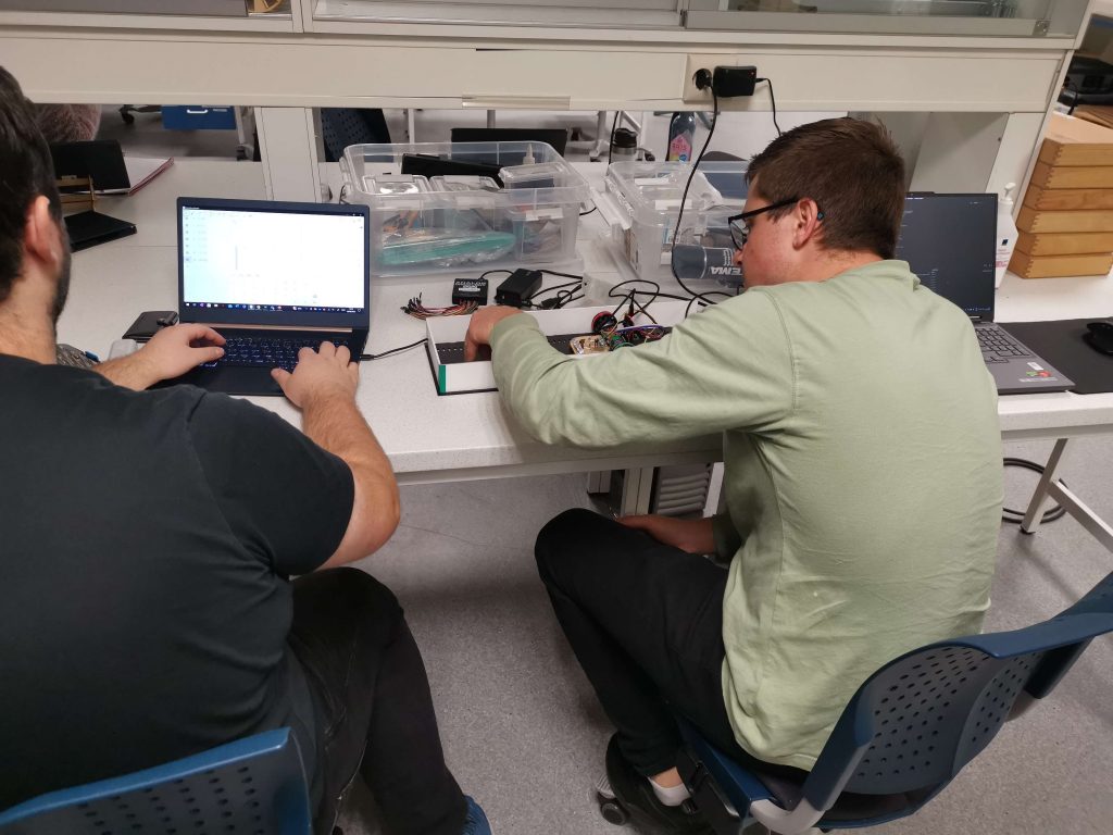
This week we finally got the Micromouse driving.
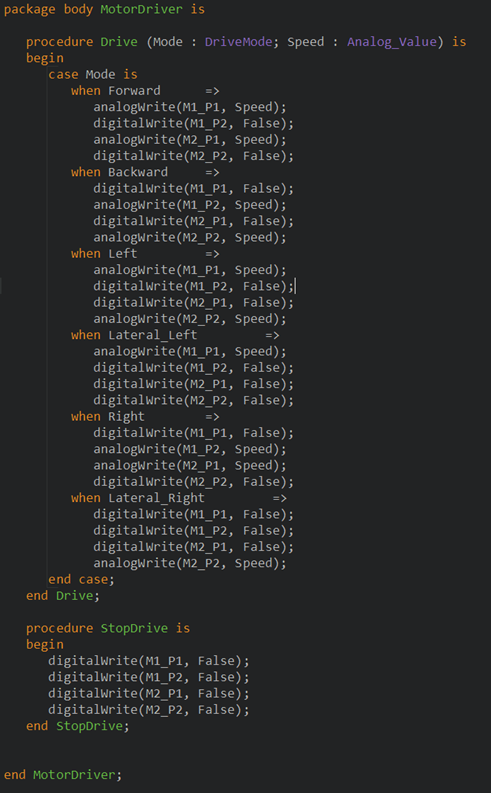
I expanded the motordriver package I made to include a “DriveMode” type that has different directions for driving, as well a procedure that writes analog values to the right pins to actually make the motors spin.
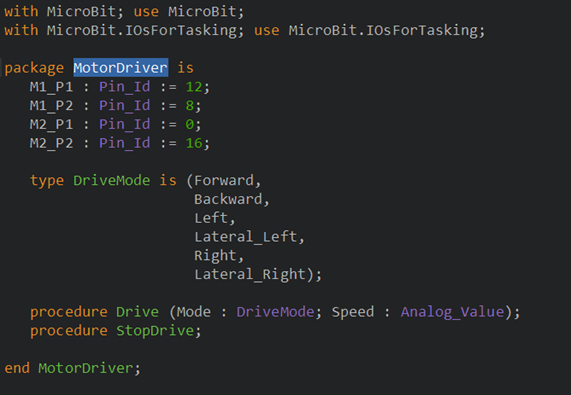
In addition, in the “main” file I also integrated the IR sensor, so that it reads values form the IR receiver and calls procedures from my MotorDriver package depending on the analog values received from the IR receiver:
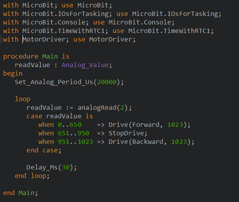
The higher the analog value, the closer the IR receiver is to a wall, because it is receiving more light.
The result of this code:
The micromouse stops when the analog values are between 651 and 950, and reverses when the values go over that.
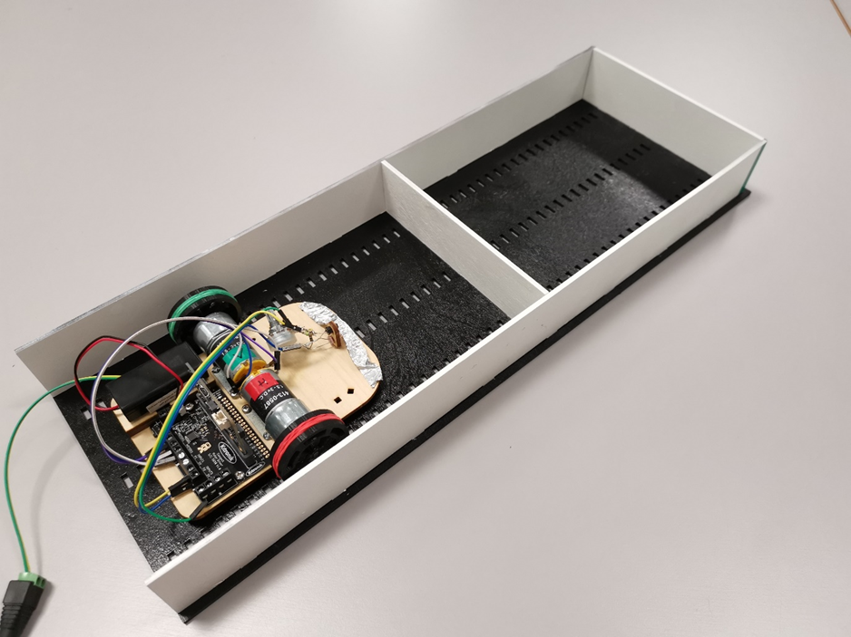
Also, me and Andreas calibrated the IR sensor, testing which analog values correspond to which distances in real life. This is where Marte’s test track came in handy!
Marte
The MVP is ready for demo on the midway evaluation Monday morning! 😊
All groups will present their work so far on Monday morning the 2nd of october. After the presentations, our group will take an autumn break from the project, and continue working on the project october 9th.
This week:
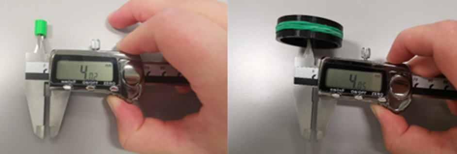
On Monday morning I recieved the three test hubs from Richard. The test hubs I sent were modelled 3-5% bigger than the drive shaft, but they were still too narrow because of shrinkage when 3D printing. I then sent three more, Richard was very productive and delivered them very fast, and the one which were modelled 7% wider than the drive shaft fitted.
When knowing which hub size needed, I sent the 3D model of the whole wheel to Richard, who started printing it straight away, resulting in a finished wheel that could be assembled on the MVP on Monday.
The chosen hub and the printed wheel had a small deviation. This had a small impact when assembling the wheels, being a little less tight, but it is sufficient enough for the MVP.
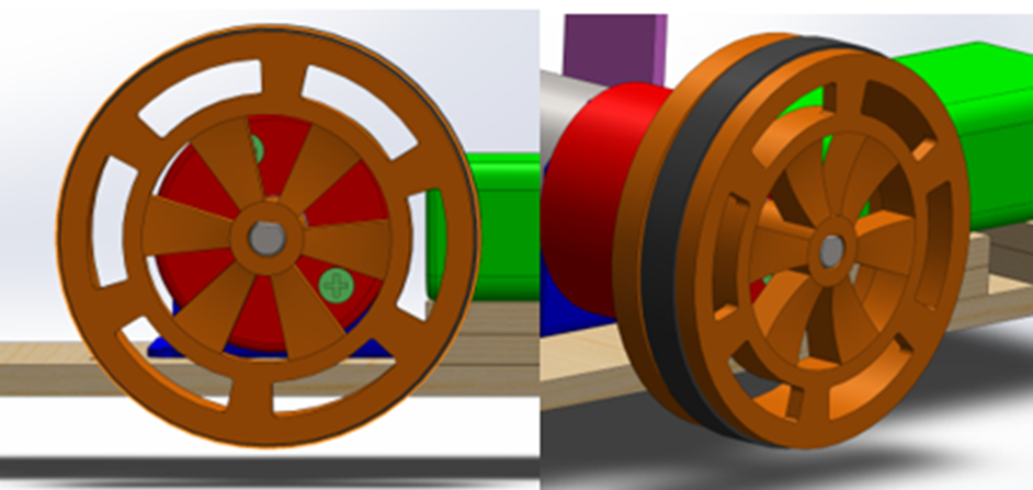
On the new wheel design I made sure to make it possible to disassemble the gear box with the wheels assembled.
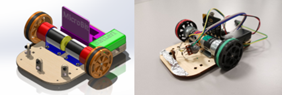
Our MVP! The rubber bands surrounding the wheels will later be replaced with one 3D printed rubber ring for each wheel.
After assembling the wheels, and handed over the MVP to the electrical and software engineers to countinue their magic, I started making a test track.
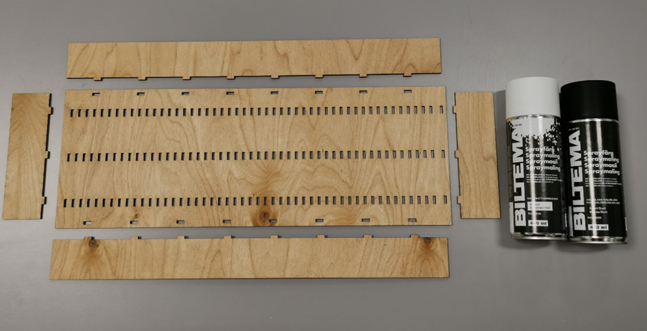
I 3D modelled the test track in SolidWorks and used plywood in the lasercutter. I then used non gloss spraypaint (IEEE competition rules), black for the floor and white for the walls.
Vendel
This week we managed to make a functioning prototype! The car still has little in the way of brains, but I think it was a big sigh of relief for the whole team when the MicroMouse took its first stabs at driving.
Apart from passing protractors and posing for pictures, my work this week has been filling the mouse’s brain with understanding, where the boys have been focusing on the interface between the world and the machine. I have successfully made a program that can populate a map with a center goal, and each cell’s distance from it in pure taxicab geometry.
Next week, apart from being a week full of presentations (I thought fall break was a thing, apparently not!), the focus for my part will be to finish up the map module with support for walls and getting it all ported to ADA so it can interact with the rest of the script. I also need to time my function after having it ported, so we can determine the tolerances on the real time system and see how fast we can actually have this mouse going without running too fast for its own brain.
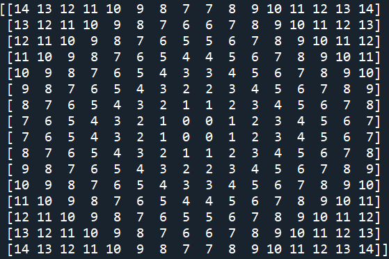
While in the wrong language, the functioning code to populate an arbitrarily large maze map with distances is as follows:
[sett inn FFmap.py her]
I’m pretty proud of it being less than sixty lines, though it might look significantly different in ADA. This produces the following output for a 16×16 wall-less maze: