Hewwo Blog :3
Another week featuring more progress, struggles and results. 💪😉
Not going to keep you waiting, here are the individual contributions for this week!👷♂️
Jonathan 🧙♂️
Agenda:
- Research position tracking
- Set up C++ environment
- Familiarize with the CODAL microbit C++ library
- Complete presentation
Position tracking
In our efforts to make the robot autonomously solve any maze, having position tracking could significantly improve our ability to interface with software.
But the robot is blind… How do we track its position??
We have to use some kind of sensor fusion. The micro:bit is equipped with accelerometer and compass sensors. Ideally the accelerometer gives us the direction in which the microbit is accelerating relative to the microbit, and the compass gives us the direction the microbit is heading relative to the magnetic field on Earth.
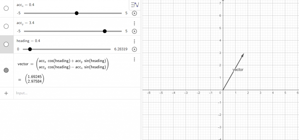
If we assume the data from these sensors are always accurate, we can create acceleration vectors that we can use to determine the robots position at any time (check geogebra equation):
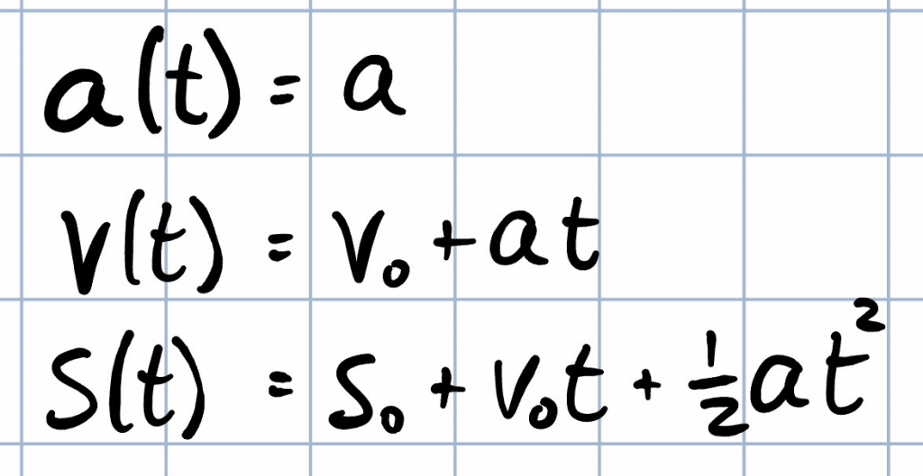
The way we convert from acceleration to position are simple physics equations as follows:
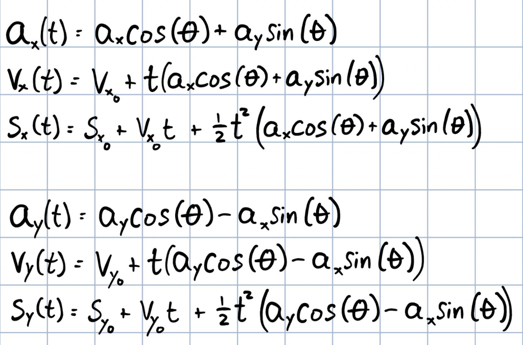
If we translate from values relative to the micro:bit to values relative to the magnetic field, the equations for x and y coordinates look as follows (keep in mind we only care about the xy-plane):
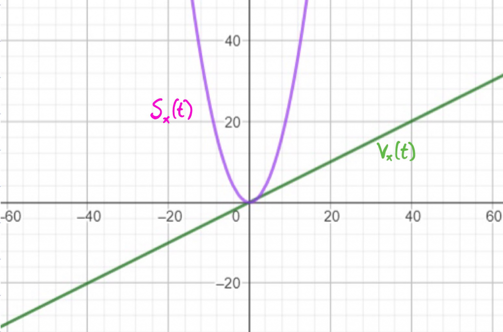
If we input an acceleration of 0.5, the velocity and position in the x-direction develops like this:
A big issue with this solution is that we assume the sensor data is noise-free. Noise will play a significant role when using cheap sensors and will accumulate over time. After a google search, I’ve found that keywords targeting this kind of problem are low-pass filter, zero-offset correction and calibration. Will look into that in the next iteration…
Mats 🧑💻
Group organisation
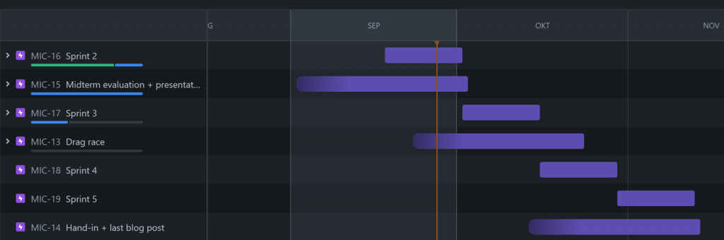
This week I started by reorganising the Jira and adding a roadmap using Epics for our group. This makes it easier to prioritise tasks in the Kanban board and see what still needs to be assigned or finished.
Development workflow
I’ve finished the CMake setup and written documentation for setting up an environment capable of both compiling the simulator for desktop platforms and the firmware for the micro:bit v2.
In addition thanks to the Cortex Debug VSCode extension making it easy to upload and launch the debugger over CMSIS-DAP using pyocd just by pressing F5 after setting up launch and task configurations.
DFR0548 motor driver
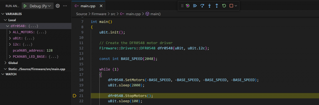
I decided to prepare and write a dedicated C++ driver for the DFR0548 using CODAL based on the datasheets and the Ada version of the driver written by Steven before Monday. On Monday after flashing it, turning on power and resuming the program from the debugger:

Time to debug! 🙇♂️
After looking over the code I was unable to find something obvious so I decided to strip down the code into the bare minimum required and mess with MicroPython. I ended up eliminating differences one of them being setting the bits of the MODE1 register using a bitflag enum instead of just a const value of multiple bitflags, here I noticed I had forgotten to set the ALLCALL register 🤦♂️, shortly after the motors started spinning. Time to return to C++ and try again… and! nothing again.

After looking over the code I could not find any noticable differences, then I thought, MicroPython uses CODAL internally so maybe it does something extra? Sure it did. Turns out I hit the exact same issue Steven experienced while creating the Ada driver, I had used the 7-bit address but the CODAL I2C function expected me to shift the 8-bit address parameter one bit to the left…
After that it finally started working! 🏎️
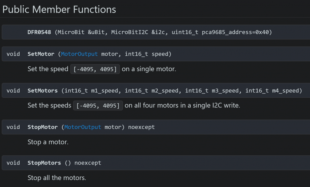
Now all the motors or just a single one can be updated in just a single i2c write in the CODAL Micro:Bit API using these methods:
Iver👴
This week I have been setting up an IR sensor. The intention is to do some tests to see if we will be using IR instead of sonar on the sides of the mouse. I started by watching the lecture from UCLA that Steven provided for us. From there I used the schematics to make circuit for the sensors.
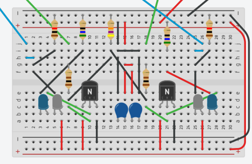
As you can see. This circuit contains two sets of diodes, making up two sensors. This is to test if it can be used to see if we can calculate the angles of the walls parallel to the mouse. When both sensors give the same value, the mouse is perfectly parallel to the wall.
The only thing to do now is to test the sensors with some code!
Next week on Keeping Up With the MicroBros 🤳
- Mid-term presentation time 😅
- More work on integration with the MicroMouse, tracking, sensors and maybe even some communication! 🤖
- More debugging? 😭