Hi Dronesonen! 😊
This week we have conducted the following efforts:
Discipline – Software:
Erik-Andre Hegna:
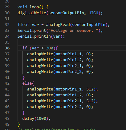
On monday I worked a lot with Hugo on trying to make the sensor less sensitive to noise, and getting a more stable reading. I used the code below to see how the sensor value reacted to stimuli, and it was very unstable. I then used a lot of time talking with other groups on how they had done it.
We got some good alternative ways to build the sensor, and new ways to test it. This resulted in a new sensor circuit and a lot better reading!
On Wednesday the whole group worked on making the MVP and presentation ready for next Monday. That means connecting the radio transmitter and receiver to the microbit, reading sensor value, and making the motors work according to radio commands AND sensor values.
Next week, I would like to implement more algorithms to the microbit (Now that we have the radio and the communication working between sensor and motor). It is now time to code!
Lars Leganger:
This week we tested our MVP and made our presentation for the midway presentation. I adjusted the receiver code, so my Microbit that sends the command to the car now also receives data from the sensors. It’s still some noise from the sensors so the argument for when to print what is not accurate yet.
Ask Lindbråten:
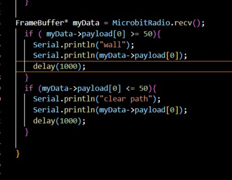
This week our goal was to complete the integrated test of our MVP. On Wednesday I met up with the group and began modifying the script for the Microbit, that’s placed on the micromouse, so it could function as both a sender and receiver. Here’s the modified script:
#include <Arduino.h>
#include <NRF52_Radio_library.h>

NRF52_Radio MicrobitRadio = NRF52_Radio();
FrameBuffer *myDataSendData;
const long interval = 1000; //1000 ms
const int MSGSIZE = 2; //max 32
uint8_t msg[MSGSIZE]; //since global, it will init to all zero's.
static long currentMillis = 0;
const int frequency = 7; //2.407GHz Radio
const uint8_t group = 1;

int MP1_1 = 12;
int MP1_2 = 8; //motor pin 8.
int MP2_1 = 16;
int MP2_2 = 0;
int IR_receiver = 1;
int IR_emitter = PIN_BUTTON_A; //right side pin 8
uint8_t analog_value = 0;

void setup() {

  pinMode(IR_receiver, INPUT);
  pinMode(IR_emitter, OUTPUT);
  pinMode(MP1_1, OUTPUT);
  pinMode(MP1_2, OUTPUT);
  pinMode(MP2_1, OUTPUT);
  pinMode(MP2_2, OUTPUT);
  Serial.begin(115200);

  myDataSendData = new FrameBuffer();
  myDataSendData->length = 5; //3 (fixed) + MSGSIZE
  myDataSendData->version = 12;
  myDataSendData->group = group;
  myDataSendData->protocol = 14;

  msg[0] = myDataSendData->payload[0];
  msg[1] = 0xFF;

  memcpy(myDataSendData->payload, &msg, sizeof(uint8_t) * MSGSIZE);

  Serial.println("Micro:Bit V2b");
  Serial.print("Frequency: ");
  Serial.print(frequency);
  Serial.print(" Length: ");
  Serial.print(myDataSendData->length);
  Serial.print(" Version: ");
  Serial.print(myDataSendData->version);
  Serial.print(" Group: ");
  Serial.print(myDataSendData->group);
  Serial.print(" Protocol ");
  Serial.println(myDataSendData->protocol);

  MicrobitRadio.enable();

  MicrobitRadio.setFrequencyBand(frequency);
  MicrobitRadio.setGroup(group);

  Serial.println("");
  Serial.println("READY");
  Serial.println("");
}

void motorControl(uint8_t n);
void stop();
void driveForward();
void leftRotate();
void rightRotate();
void reverse();
void reactToMeasure(uint8_t a);

void loop() {

  digitalWrite(IR_emitter, HIGH);
  analog_value = analogRead(IR_receiver);
  myDataSendData->payload[0] = analog_value;

  if (millis() - currentMillis >= interval){
     Serial.println("Micro:Bit V2b sending: ");
     Serial.println(analog_value);

     MicrobitRadio.send(myDataSendData);
     currentMillis = millis();
  }

  FrameBuffer* myData = MicrobitRadio.recv();
  if (myData != NULL) {
     motorControl(myData->payload[0]);
     delete myData;
  }
}

void leftRotate(){
  analogWrite(MP1_1, 180); //accelerate the right wheel motor.
  analogWrite(MP1_2, 0); //set reverse pin for motor 1 to low.
  analogWrite(MP2_1, 0); //set acceleration pin for motor 2 to low.
  analogWrite(MP2_2, 180); //Reverse the left wheel or motor.
}
void driveForward(){
  analogWrite(MP1_1, 180); //accelerate both wheels.
  analogWrite(MP1_2, 0);
  analogWrite(MP2_1, 180);
  analogWrite(MP2_2, 0);
}
void rightRotate(){
  analogWrite(MP1_1, 0);
  analogWrite(MP1_2, 180); //Reverse the right wheel.
  analogWrite(MP2_1, 180); //accelerate the left wheel.
  analogWrite(MP2_2, 0);
}
void stop(){
  analogWrite(MP1_1, 0);
  analogWrite(MP1_2, 0);
  analogWrite(MP2_1, 0);
  analogWrite(MP2_2, 0);
}
void reverse(){
  analogWrite(MP1_1, 0);
  analogWrite(MP1_2, 180);
  analogWrite(MP2_1, 0);
  analogWrite(MP2_2, 180);
}

void motorControl(uint8_t n){
  switch(n){
    case 1:
    reactToMeasure(analog_value);
    Serial.println("<reactToMeasure was activated>");
    break;
    case 2:
    leftRotate();
    Serial.println("<Left rotate was activated>");
    break;
    case 3:
    rightRotate();
    Serial.println("<Right rotate was activated>");
    break;
    case 4:
    stop();
    Serial.println("<Stop was activated>");
    break;
    case 5:
    reverse();
    Serial.println("<Reverse was activated>");
    case 6:
    driveForward();
    Serial.println("<Drive forward was activated>");
    default:
    Serial.println("<Invalid input>");
  }
}

void reactToMeasure(uint8_t a){
  if (a >= 25 && a < 40){
    stop();

  } else if (a >= 40){
    reverse();

  } else {
    driveForward();
  }
}
Changes made:
- Added the sender-functionalities of Steven’s radio library.
- Passing analog-values, instead of either 0’s or 1’s, to the motor-pins to better control the motor-speed.
- Added IR-sensor measurements to the payload array of the data-packet to be forwarded to the other Microbit. This addition is necessary if we want to monitor and view essential information about the maze, including its clear paths and walls, as well as the mapping- and shortest-path calculation process.
- Added a ‘reactToMeasure()’ function that activates based on the forwarded byte from the other Microbit and utilizes an IR-measurement to conduct an appropriate action.
Potential objectives for next week:
- Incorporating measurements from 4 sensors (Filtering could potentially be needed…)
- Continue developing the algorithms from week 4:
- Combine and migrate them to Visual Studio Code.
- Implement IR – sensor measurements.
Discipline – Electrical:
Hugo Valery Mathis Masson-Benoit:
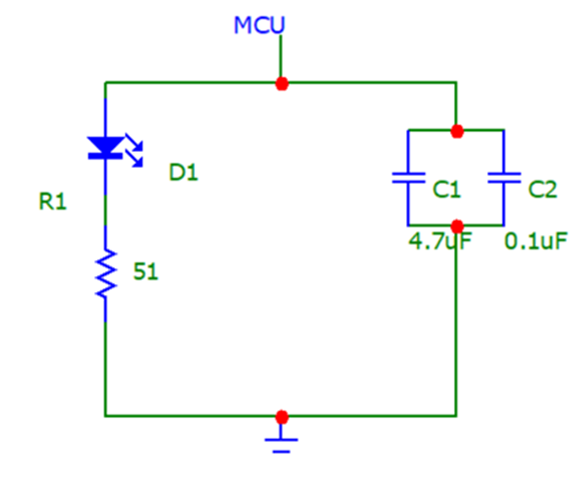
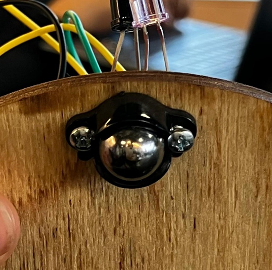
The objective for this week was to control the motors by using the data received by the sensors to complete the MVP. The information from the sensors weren’t really good and had a lot of noise, this made them unusable. So, I tried to simplify the system, and ended up redoing it all. To simplify the system, I removed the VCC input for the emitter, to have it supplied directly by the Microbit. This way we can remove the MOSFET and directly control the IR emitter. I also put the bypass capacitor on for the MVP, to reduce the general noise. Now the capacitors are no longer an “option”, to have a good signal they are mandatory. Here is the new electrical design for the IR emitter:
A picture of the sensors and the bypass capacitor on the MVP:
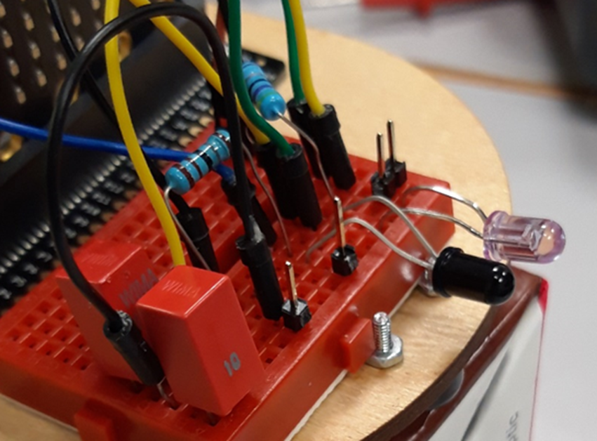
(I did not change anything about the IR receiver, it’s the same design as before.)
We also discovered that the 9 volts battery is quickly consumed, so we need to keep an eye on it when we try something with the prototype.
Conclusion:
Now the Microbit is receiving usable data, and the software engineers were able to do some programming using it. It’s a success.
Objective for next week:
Connect four sensors to the prototype to make them communicate with the Microbit, and see if more components are needed.
Jemima Niquen Tapia:
This week as I thought the only thing missing was the battery problem, that wasn’t working well, I just did some research for making the sensor work better. So, having an amplified sign so using amplifiers, so it could be more accurate. As we changed the IR sensor circuit, we have good signs coming from the sensor it will be not needed at the moment. I also studied for the presentation for Monday, some of us have met and have put in common the ideas and have split the slides. We have talked about what’s the next step after the MVP prototype.
Discipline – Mechanical:
Cesia Niquen Tapia:
This weekI’ve been thinking about the traction on the wheels and alternative ways to help the problem. I also have assembled a provisional element so that the movement of the prototype is possible. This is provisional because as we said before the main idea is to print our own design which fits perfectly with our dimensions and bring balance and accuracy to the micromouse.
A little bonus treat… 😋🍫
Here’s a video showcasing our MVP!
This concludes our blog post for week 6, see you next week!😊
Best regards,
Group 4