Lets tune in to Turret Syndrome this week and take a look at some of the progress our group has achieved this week!
Mats Bergum
Unfortunately, at the start of the week, we found new information about the motor controller and Raspberry Pi, making the PCB I and Harld designed insufficient. Also, we found that the time frame for the project was too tight to 100% say that it would be finished on time.
So, I moved my focus on the power delivery to all parts of the systems. First, I played with the idea of making my own battery cell to power the system. However, when talking to Steven and Henning, I discovered that USN does not have access to a spot welder and that getting the battery management system in time was hard. So, I had to go for a less slim design option using a 24V battery and having a +5V regulator to power all the different components.
So, in this regard, I mapped the expected power consumption for the components, only missing the trigger system. I did not know what motor would be used.
Other things I did:
Me and Ole tested all the stepper motors with the motor controllers and found out how to control the speed of the motor with great accuracy. Also found out that the motors work better when using a supply voltage of 24V instead of 12V.
Harald Berzinis
This week I have been designing the new shooting mechanism. This 2.0 version should be sturdier and should withstand way more force generated by the rubber bands. The thought behind this mechanism is to have modularity for prototyping and adjustments.
Initial CAD design:
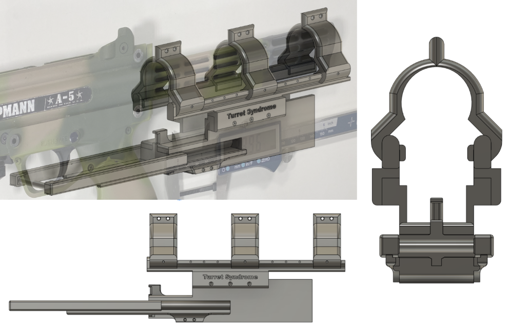
The entire concept is still in progress. I will need to make the servo mechanism which activates the bolt.

Main body for the mechanism, added screw holes for components that get connected to the main body, in order to have a sturdier build.

This rail holds the mounts for the buttstock of the paintball gun. There are small holes which can be used to fasten the mounts, shown in the next picture. Assembly should be easy for the mounts as they are just supposed to be glided on.

This is the mount component that goes on the buttstock of the paintball gun, where two small screws can be placed through it to secure the mount firmly against the buttstock. There is also a hole at the lower side, where a screw can be placed to bind the rail and the mount together. In addition, these will be printed in two parts, one for each half and screwed together at the top.
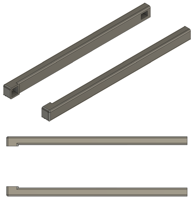
These extensions of the bolt are mounted directly on the bolt and glued together. This component also rests on another rail, so it does not wobble around when fired.

The actual part that hits the trigger. This gets glued together with the bolt extension.

This is the bolt itself, where the bolt will get suspended by rubber bands. In this iteration you can see that I have increased the extrusion where the rubber bands are placed, so it does not break itself.

This is the last component for this week, this rail helps the bolt extension to not wobble around and provide stability as previously said. It gets screwed together with the body.
Next week:
I will try to further work on the mechanism so we can start 3D-printing, assemble and further test it. The most challenging task next week will be making the bolt activate from a servo, this is because I am trying to design a way more sturdier version than the previous one. Furthermore, I have sliced some of the parts and it looks that printing time for this mechanism can be more than 40 hours of printing on my Prusa MK3s, which means we will probably need multiple printers.
Christopher Daffinrud
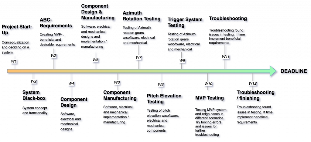
This week, I took the lead in preparing for our mid-way presentation next week. On Monday, after a planning session, I organized our future sprints, outlined the upcoming weeks, and created a long-term project completion plan. Up until now, we’ve mostly worked on individual components, but as we move towards assembling and testing them together in the upcoming sprints, it’s crucial that we all adhere to common deadlines for our individual tasks.
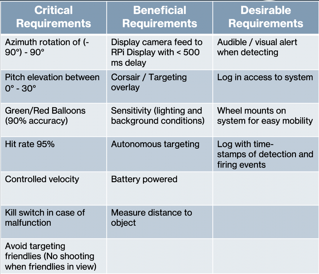
We also iterated on our ABC-requirements. Due to changes made underway other realizations our ABC-requirements now look like this:
Next week I will focus more on software aspects as PID-regulators for movement, and start to set up a testing environment in Unity.
Ole Eirik S.Seljordslia
As per our timeline we wanted to start testing the azimuth rotation for our turret. The physical manufacturing is mostly done so we could start integrating motors into the sun gear. I spent the first part of the week implementing a class that could represent the motor driver used to control our motors.
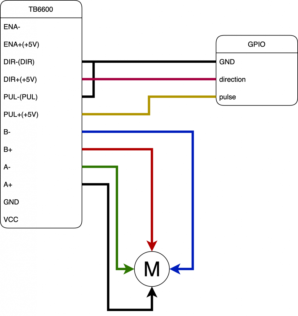
We are using the TB6600 motor driver, this is a two phase stepper motor driver with quite a few settings. It can be wired up in different configurations as per DFRobot’s user guide. We chose to wire the controller up in a common cathode configuration, this resulted in minimal wiring. After some testing I found out that the driver’s EN-pin does not need to be activated, it is activated as default. This resulted in the following wiring:
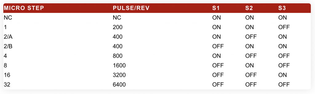
The motor driver has a DIP package with six switches that determines its settings regarding current and microstep. Settings for current sets the upper limit for peak and continuous current, while microstep sets the angle that the motor should move per step. Each stepper motor comes with a step angle (typically 1.8 degree per step), the motor driver will then divide this step into microsteps. So the resulting angle per step will be motor angle/microstep . We were not able to verify the angle per step by measuring it, but we could see the total number of pulses needed to perform a full revolution increased when we increased the microstep setting.
The following code snippet gives control signals to the motor driver from the raspberry pi. First the direction pin is either set to high or low, determining clockwise or counterclockwise rotation. Then the pulse pin will be pulsed(50% duty cycle) a given amount of periods(steps), with the period time determining the frequency/speed of the rotation.TB6600 supports up to 13 KHz, to support higher frequencies the motor controller needs higher supply voltages. We used frequencies up to 3 KHz with a supply voltage of 24VDC.
To achieve the timing for the period, sleep delays are used, this should be changed later to use a non-blocking implementation.
1 2 3 4 5 6 7 8 9 10 11 12 13 14 | def drive(self, steps: int, direction: Direction = Direction.CLOCKWISE)->None: """Drive motor in one direction for a number of steps Args: steps: Number of steps to rotate direction: Direction to rotate. Defaults to Direction.CLOCKWISE. """ GPIO.output(self.__direction_pin, bool(direction)) for step in range(steps): GPIO.output(self.__pulse_pin, GPIO.HIGH) sleep(self.__period/2) GPIO.output(self.__pulse_pin, GPIO.LOW) sleep(self.__period/2) |
The remainder of the week was used for documenting the implementation of the motor driver class and preparing for the presentation. For this we will demonstrate object detection in real time on the raspberry pi.
Hannes Weigel
The goal for this week was to complete the azimuth drive. Initially, this goal was achieved, but we soon began discovering problems with 1 of our stepper motors.
On their own, each stepper motor functioned flawlessly and drove the azimuth system. In tandem with two motors, we had no problem as well.
But as we introduced a third motor, we discovered the third motor would sporadically change directions and lock up the gear system.
As this was only the case for one exact motor, we began troubleshooting if said motor was faulty.
My time troubleshooting the motor was cut short, as I was headed to Trondheim on Thursday to view the unveiling of Propulse their new rocket.
Further work
Next week will focus on fixing the third motor of the azimuth drive, and hopefully get a prototype of the pitch drive working.