Andreas
I have spent this week implementing solution for motor control and ensuring proper filtering of the sensor so that we have the least amount of noise possible. Most of the time has been spent making a basic PID controller that inputs the current positional data and the wanted position so that we can drive towards the position we want. This should be able to use the compass that is in the MicroBit to give the controller input, though we have been warned it is not extremely accurate. One of the bigger issues is how we can continually update the position in edge cases where the IR sensors don’t have the range to detect the wall it is driving towards.
So far, most of the code is an example I can use as a framework for the completed code, as I am not very used to programming for the MicroBit. As well as this shortcoming it is also not decided if we want to use another form of control than a PID controller, though this is one of the simpler ways to implement a controller.
For now, the PID controller is the easiest option, and I will be looking into the other options the next week so we might find the optimal controller. I might also begin making the schematic and boards for the PCB printer.
// Define motor pins
int motor1A = 2;
int motor1B = 3;
int motor2A = 4;
int motor2B = 5;
int threshold = 1; // Value subject to change after calibrating the IR sensor


// Define PID constants
double Kp_linear = 1.0;
double Ki_linear = 0.1;
double Kd_linear = 0.01;
double Kp_angular = 1.0;
double Ki_angular = 0.1;
double Kd_angular = 0.01;

// Define variables for PID control
double setpoint_linear = 0.0;
double setpoint_angular = 0.0;
double position_linear = 0.0;
double position_angular = 0.0;
double prevLinearError = 0.0;
double prevAngularError = 0.0;
double integral_linear = 0.0;
double integral_angular = 0.0;

// Define variable for rate limiter
double maxRateOfChange = 50.0;


void setup() {
    pinMode(motor1A, OUTPUT);
    pinMode(motor1B, OUTPUT);
    pinMode(motor2A, OUTPUT);
    pinMode(motor2B, OUTPUT);
}

void controlMotors(double linearOutput, double angularOutput) {
    // Calculate motor speeds
    int speed1 = int(constrain(linearOutput - angularOutput, -255, 255));
    int speed2 = int(constrain(linearOutput + angularOutput, -255, 255));

    // Apply rate limiter to ensure no jump in motor output
    static int prevSpeed1 = 0;
    static int prevSpeed2 = 0;

    if (abs(speed1 - prevSpeed1) > maxRateOfChange) {
        if (speed1 > prevSpeed1) {
            speed1 = prevSpeed1 + maxRateOfChange;
        }
        else {
            speed1 = prevSpeed1 - maxRateOfChange;
        }
    }

    if (abs(speed2 - prevSpeed2) > maxRateOfChange) {
        if (speed2 > prevSpeed2) {
            speed2 = prevSpeed2 + maxRateOfChange;
        }
        else {
            speed2 = prevSpeed2 - maxRateOfChange;
        }
    }

    // Set motor directions and control speed
    digitalWrite(motor1A, speed1 >= 0 ? HIGH : LOW);
    digitalWrite(motor2A, speed2 >= 0 ? HIGH : LOW);
    analogWrite(motor1B, abs(speed1));
    analogWrite(motor2B, abs(speed2));

    // Update previous speeds
    prevSpeed1 = speed1;
    prevSpeed2 = speed2;
}
void loop() {

    // Need code from Vendel to give me the wanted position and the wanted position so both the angular and linear position from the set point can be calculated


    // Calculate linear error and angular error
    double linearError = setpoint_linear - position_linear;
    double angularError = setpoint_angular - position_angular;

    // Calculate PID control for linear motion
    double linearOutput = Kp_linear * linearError + Ki_linear * integral_linear + Kd_linear * (linearError - prevLinearError);

    // Calculate PID control for angular motion
    double angularOutput = Kp_angular * angularError + Ki_angular * integral_angular + Kd_angular * (angularError - prevAngularError);

    // Control the motors using PID control and rate limiter
    controlMotors(linearOutput, angularOutput);

    // Update the previous errors for the next iteration
    prevLinearError = linearError;
    prevAngularError = angularError;


    delay(100);
}
Bendik
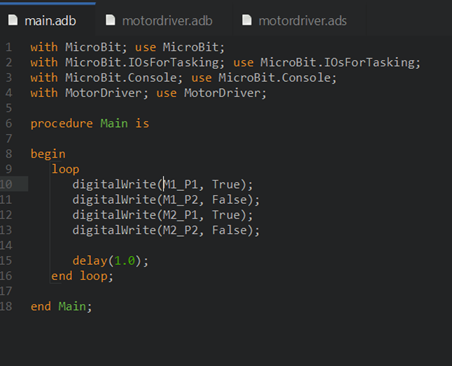
This week has been the week of faults. I used Monday to program the motors in C++. Something as simple as getting both of the motors to run at the same time was hard. Both of the motors would go backwards, but forwards – only one. I tried changing the connections around (plus to minus and vise versa), didn’t work. I tried measuring the voltage on the motor that wasn’t moving. It was not receiving any voltage. I suspected that there was a fault in the motor driver board, but before I jumped to conclusions I wanted to make sure that it was correctly programmed and that the pins were receiving the correct high and low signals.
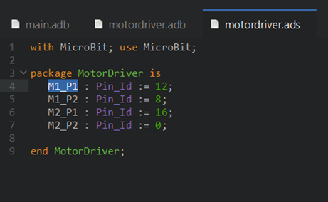
The motor driver board uses 4 pins from the micro:bit to control the motors – Pins 12, 8, 16 and 0. I located the problem with being pin 16, as this was the pin that wasn’t sending out voltage like it should have. Turns out there is a bug in platformIO that hinders pin 16 from being able to be set to HIGH. Using ADA and GNATStudio solved the issue, I think we will be using that from now on.
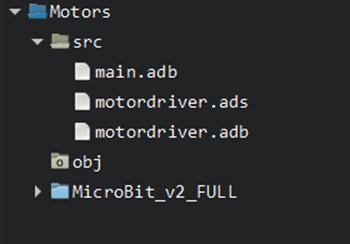
I made a simple ADA package called “MotorDriver”. Here is where all the functions such as “Backward”, “Forward”, “Left” etc will be implemented.
On Sunday I looked into using the compass (or magnetometer) on the Micro:Bit. As there is no driver for ADA yet, I tried to use PlatformIO. I tried 5 different libraries, some for the LSM303AGR and a couple for MAG3110, but I could not get any of them to work correctly. I would either get no values at all printed to the serial monitor, or just static values that never changed. So I think I will put this aside for now and work on other ways for the micromouse to drive straight and turn 90 degrees etc. Using IR sensors, and possibly wheel encoders?
That’s it for now.
Marte
This week has been a downturn, unfortunately, I failed to get the hardware for the MVP finished this week as planned. The wheels could not be assembled to the MVP due to a couple of incidents:
- It was impossible to drill accurate holes in the wheels from the toy car (even when using a lathe)
- New 3D printed wheels would not fit because of the shrinkage that occurs when 3D printing, and I did not consider this in my 3D model.
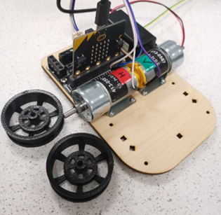
First, something that did work out this week; Fixing an interference problem in the MVP between a couple of the wires connected to the Kitronik and the battery package.
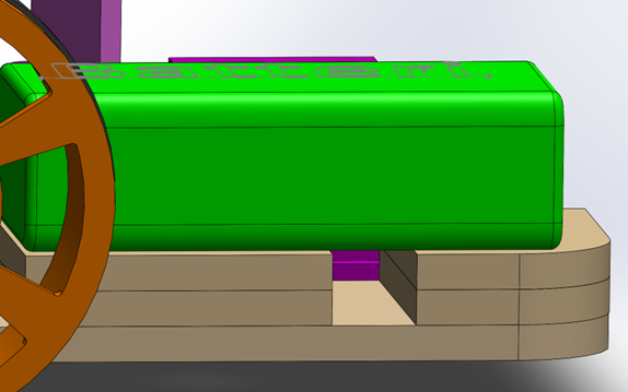
Originally the battery package was assembled at the same level as the Kitronik. Adding a thickness of two plywood plates, each 3.5mm thick, gave an elevation of 7mm.
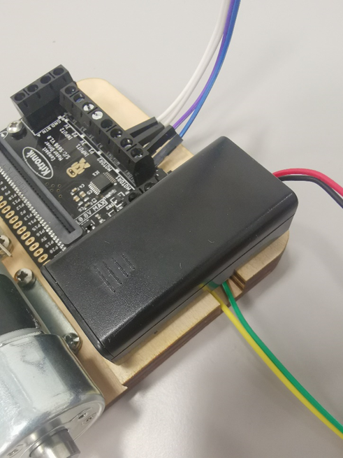
The final result after using the laser cutter to produce the parts, and assembled it with glue. It worked out great, and the green and yellow wires have free passage underneath the battery pack.
Back to the wheel issue.
On Monday afternoon I got some help from the lab engineers Tobias and Richard to use the lathe for drilling holes in the wheels from the toy car. Richard set up a type of clock when leveling the part in the machine, and it was very challenging to get the part perpendicular to the drill. The wheel yielded when the drill made contact, resulting in the hole not being centered.
Probably two main reasons for the failed result: A plastic part is not ideal for the lathe, and the wheel from the toy car had flaws like being a little crooked, and flaws from the manufacturing technique.
It was an interesting experience to use the lathe, despite of the poor final result.
After throwing away the wheels from the toy car, I 3D modelled a wheel, and sent it to Richard to 3D print on Monday evening.
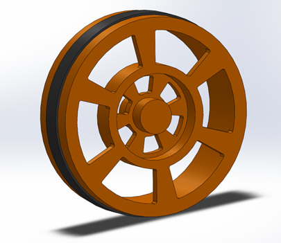
3D model In SolidWorks of the wheel assembly. A black rubber ring surrounding the rim in PLA for friction.
On Thursday the wheels were finished, but they did not fit the drive shaft.
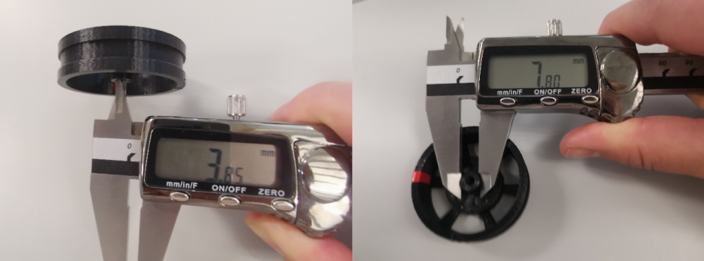
The wheels had 3.75% shrinkage in inner diameter and 3.50% shrinkage in outer diameter of the hub.
My first thought to fix this was to heat the wheel hub and press it on to the drive shaft. I spoke with Richard about the issue, and he recommended to attack the problem differently.
After getting tips from Richard, I modelled three different hubs that have measurements 3-4% bigger than the original hub and sent It to be 3D printed. Hopefully one of these hubs will fit, and then new wheels can be printed accordingly.
In addition, when trying to assemble the wheels, I noticed a poor design choice in the wheels:
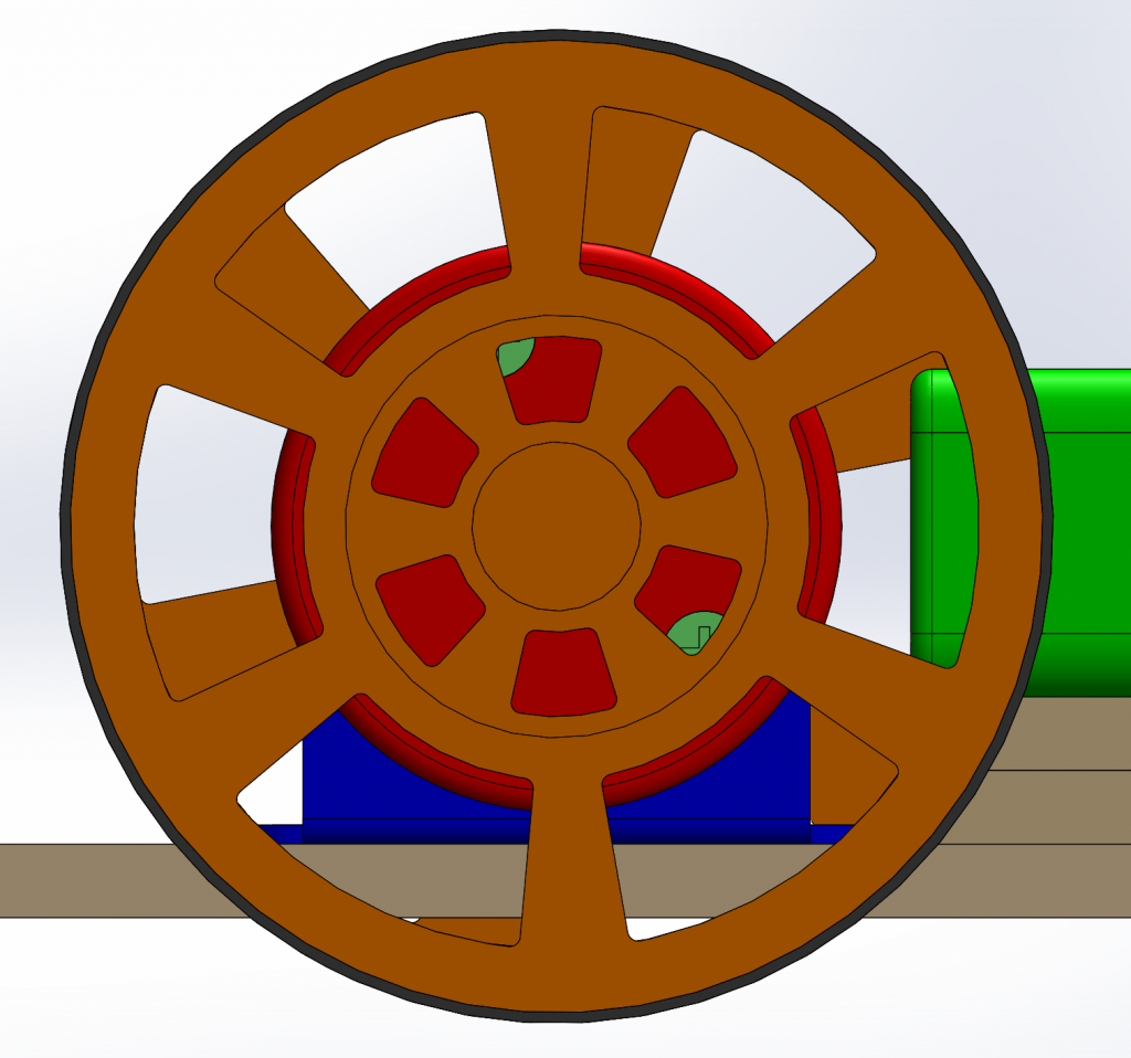
The screws in the gear head of the motor are not accessible when the wheels are attached. I will change this for the next wheels to be 3D printed.
It has been a week with a lot of content, but unfortunately we still have an unfinished MVP without wheels.
I will continue with the wheel project next week, and it is out of the question to not have a MVP on the mid-way evaluation the 2nd of October.
Vendel
This week has been consumed by various appointments for my part, eating away at the time for developing the project. I have however been thinking about how to implement the flood fill algorithm to rate the different cells in the maze to aid in pathfinding, as we are assuming following a wall will not get us to the goal of the maze. It should be really simple to decide what to do with the cells as we reach them, evaluating the adjacent cells to be “this one + 1” if they are higher, or do nothing if they are already “this one + 1”. If they are already lower than “this one + 1” shouldn’t really happen, as the “current” cell then should have been evaluated to be the other one’s “this +1”.
The issue is how to traverse the maze from the center to fill out this information to ensure that every cell is updated when the update() function is called. Checking every cell by searching for those that have values of 0, then 1, then 2 etc. will take a very long time, and likely will not actually give accurate results as it will then check cells that might have been blocked off quite happily, even though it is not true.
My second thought was to use a breadth first traversal, to move through the maze from the “root”, being one level above the center squares, and then going to every adjacent square as the children of the cell, updating them to be “this +1” in value. This should then continue until hitting a leaf node, that is, a dead end with no children, or until it hits a node that has a lower value than itself. This might need to be done to the whole map every update cycle to avoid blind spots, but on a 16 by 16 grid, this should not be too difficult a task for the microcontroller.
Next week will be for working on subjects I have neglected, and implementing this algorithm, preferably in ADA, but it could work to do it in a simpler language for testing purposes. Doing this with nodes and graphs is likely overkill, but we’ll see!