Here is our teams contributions for our project this week in sprint 5! Things are starting to ramp up!
Harald Berzinis
Harald Berzinis
This week I have been reiterating the original model, 3D-printing the trigger mechanism and further testing it.
Initial CAD-design:
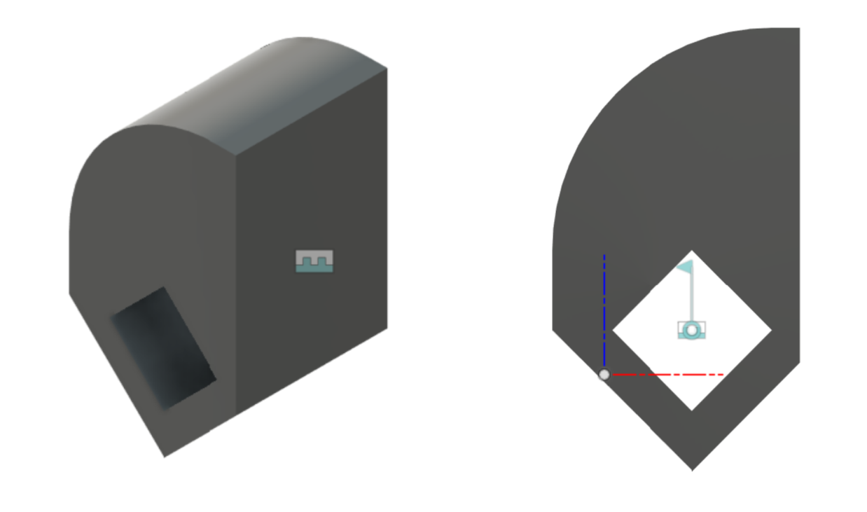
Main Enclosure:

The main enclosure that holds everything together, 3cm x 5cm x 11cm
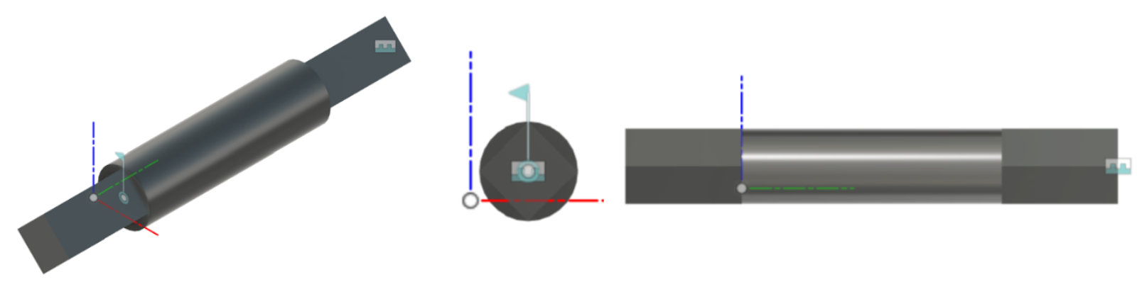
Bolt:

The main bolt that activates when the servo mechanism is initiated, converting from rotational to linear actuation for the trigger. This bolt is then suspended with a rubber band to the main enclosure.
Servo bolt:
This servo bolt gets directly mounted on the 20 tooth spur gear and the stopping component for the main bolt, this of course gets placed through the main enclosure, then glued and assembled with the other parts.
Stopping component for the main bolt:
This component is responsible for holding the main bolt at the suspended state. When the servo is initiated, this component rotates to the left and releases the suspended bolt hitting the trigger.
Trigger bolt

This is an extension for the main bolt so it hits the trigger.
20 and 10 tooth gears:

These are the 20 and 10 tooth spur gears, which makes a ratio of 2:1. These gears were reiterated due to when 3D-printing I experienced that the gears that I made were not high enough resolution, therefore I stepped down the number of teeth on each gear. These were printed at 70% infill to make sure that they do not break under load.
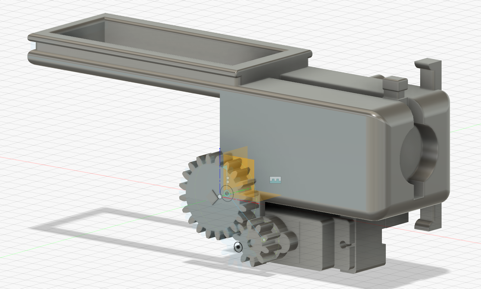
Assembly and testing:

Fully assembled trigger mechanism. In addition, we have tested it and the mechanism activates the paintball gun’s trigger. Further testing proved that the mechanism experiences tear at the main bolt and that it needs to be printed at a higher level of infill.
Next week:
The plan for me next week is to make a version of this that is mounted on the buttstock of the paintball gun, this is because we have a lot of unused space. I will then reiterate this mechanism to a more beefier version to withstand the rubber band force and further improve the stability and safety for the shooting mechanism.
Mats Bergum
Most of my time was spent watching and following this tutorial. (https://www.youtube.com/watch?v=d_TPIxPX01s&ab_channel=RobertFeranec) from Robert Feranec. Following this tutorial taught me how to make footprints and 3D models and assign them to the correct components. I also learned how to set up PCB stackup in Allegro and route the PCB in Allegro. Moreover, the tutorial also showed me how to import changes in the schematic to the existing PCB design, which can be helpful when producing my own PCB.
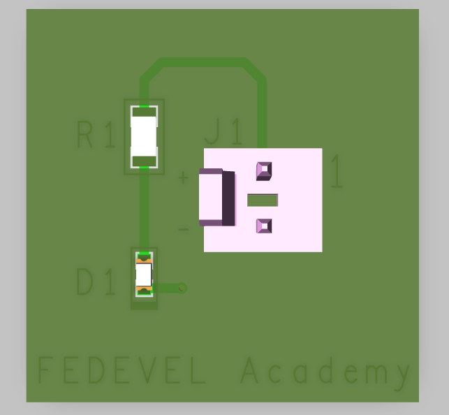
The PCB I made following this tutorial can be found below. This was done by copying what was done in the tutorial, but it was a good learning experience.
3D view of the board:
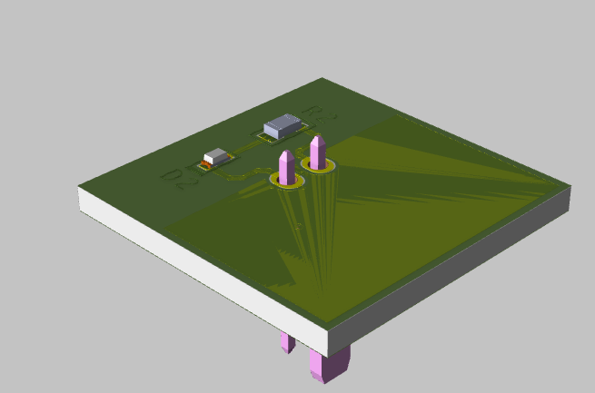
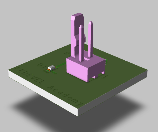
Routing:
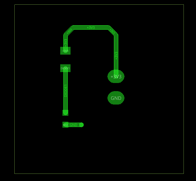
I tried to make the PCB design for our circuit, but I could not do this due to some console errors that I could not fix. Thus, I only made some footprints and 3D models for curtain components. Next week, I need to try fixing those errors and start with the routing.
Christopher Daffinrud
After severe testing using the Pi for object detection calculations, and using probably one of the most efficient models in EfficientDet we concluded in the beginning of week 5 that we would like to separate the object and color recognition calculations on an external device communicating with the Raspberry Pi over UDP.
Our new intention is setting up a local network on the Raspberry Pi allowing for UDP-communication between the Pi and an external computer with a socket. The camera feed captures from the Raspberry Pi´s web camera shall then be transferred to the external computer for computations. The external computer will then return the relevant data and coordinates needed for the Turret System to perform its actions depending on the calculations.
I iterated on my previous class diagram, now facilitating this change.
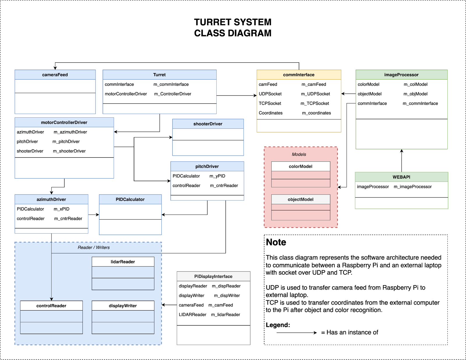
As you can see from the model the Turret and the external computer are connected through the class “commInterface”.
- UDPSocket for transferring camera frames from Pi to external computer
- TCPSocket for transferring object coordinates and relevant data from external computer to Pi
I also created a simple high-level component diagram of our system, including the component needing 5V or 12V.
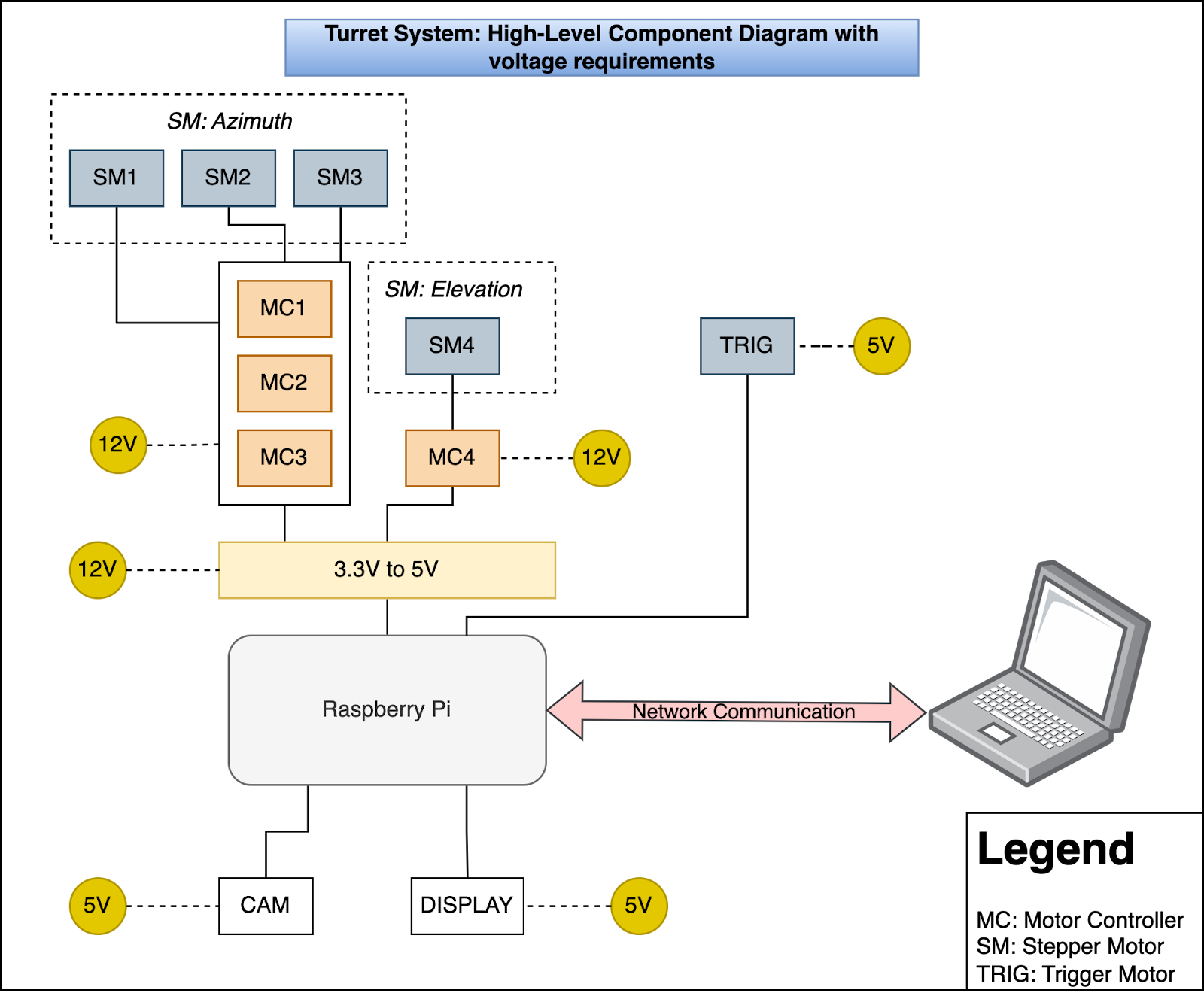
The 3.3V to 5V represents the converter circuit which Harald and Mats are developing.
All nodes with 5V and 12V are additional voltage requirements needed that will be fulfilled by creating a PCB.
The network communication channel in this model is the Local Wifi-network supplied either by the Raspberry Pi or the external computer with communication through sockets.
These diagrams allowed further specification of tasks needed to be done through Azure Devops.
Hopefully we will be able to start implementing some software solutions during this week. That will also be the main focus for software next week.
Ole Eirik S.Seljordslia
In response to the computational limitations we encountered with the Raspberry Pi last week, we took a step back to explore alternative solutions. One of the promising ideas that emerged was the concept of streaming video from the Raspberry Pi to an external computer. This approach would leverage the secondary computer’s superior processing power to handle computationally intensive tasks.
In this envisioned setup, the external computer would receive the video feed from the Raspberry Pi, process it, and return coordinates corresponding to any detected balloons within the video stream. An advantage of this arrangement is its versatility; it allows us to conveniently test the system using a regular laptop, we could also switch out the laptop at a later time.
To realize communication between the turret and the image processor, we needed a interface capable of efficiently sending and receiving frames. In practice, the external computer would act as a server hosting a socket connection through UDP, enabling the Raspberry Pi mounted on the turret to send images and receive balloon coordinates in response. These coordinates represent the predictions made by our object detection model regarding balloon locations.
During the past week, I dedicated my efforts to implementing and testing this interface between the two computers.
Our project consists of two distinct code bases: one for the turret and another for the image processor. Given that the turret’s role is to transmit frames to the image processor, I developed communication classes to interface the two systems. The following snippet is the turret’s method for sending frames:
Transmitting frames
1 2 3 4 5 6 7 8 9 10 11 12 13 14 15 16 17 18 19 20 21 22 23 24 25 26 | def send_frame(self, frame: cv2.typing.MatLike)->None: """_summary_ Send individual frames Args: frame (cv2.typing.MatLike): Frame from video stream Raises: Exception: Unable to encode frame """ return_value, image_buffer = cv2.imencode(self.__image_format, frame) if not return_value: raise Exception('Unable to encode frame') image_buffer = image_buffer.tobytes() number_of_packets = 1 if len(image_buffer) > self.__max_buffer_size: number_of_packets = int(np.ceil(len(image_buffer)/self.__max_buffer_size)) self.__socket.sendto(pickle.dumps({'packets':number_of_packets}), self.__server) left = 0 right = self.__max_buffer_size for packet_index in range(number_of_packets): payload = image_buffer[left:right] left = right right += self.__max_buffer_size self.__socket.sendto(payload, self.__server) |
This ‘send_frame’ method anticipates a ‘cv2.typing.MatLike’ input, which aligns with the output of ‘cv2.VideoCapture()’. It encodes the frame to a buffer using the ‘.jpg’ format. If the encoding is successful, it converts the buffer to bytes and determines the number of packets required based on the byte conversion. The number of packets is then sent as the first packet to the image processor, serving as an indicator of the frame’s completeness. This packet is serialized through the `pickle.dumps` function. Subsequently, segments of the image buffer are dispatched to the image processor, respecting the maximum packet size, which should be predefined and agreed upon by both the turret and image processor. The maximum packet size is determined by each computer UDP MTU, this can vary based on hardware and operating system compositions.
The image processor, in turn, implements a complementary method to receive frames:
Receiving frames
1 2 3 4 5 6 7 8 9 10 11 12 13 14 15 16 17 18 19 20 21 22 23 24 25 26 27 28 29 30 31 32 33 34 35 36 37 38 39 40 | def receive_frame(self)->np.ndarray: """Will return next frame from a video stream Returns: Array of pixels """ buffer, address = self.__socket.recvfrom(self.__max_buffer_size) # try: # frame_info = pickle.loads(buffer) # except: # print('Missed frame information') # return None if len(buffer) > 500: return None frame_info = pickle.loads(buffer) if frame_info: number_of_packets = frame_info['packets'] packets = bytes() for packet_index in range(number_of_packets): payload, _ = self.__socket.recvfrom(self.__max_buffer_size) packets += payload return self.__process_frames(packets) def __process_frames(self, buffer)->np.ndarray: """Transform frame. Args: buffer: Incoming buffer representing a frame from video stream. Returns: Transformed buffer of frame """ frame = np.frombuffer(buffer, dtype=np.uint8) frame = frame.reshape(frame.shape[0], 1) frame = cv2.imdecode(frame, cv2.IMREAD_COLOR) frame = cv2.flip(frame, 1) return frame |
The ‘receive_frame’ method begins by receiving a buffer from the turret. It extracts frame information from the first packet, particularly the number of packets to expect. To address potential challenges like missing initial packets, we employ a size threshold to distinguish between the initial information packet and subsequent data packets. This could have also been handled by trying to process the packet and possibly catching an exception. I opted from this as I expect it to be a more time consuming solution opposed to checking the length.
Following this, each packet is collected into a byte array before being processed by the internal `__process_frames` method, which ultimately returns a NumPy array suitable for object detection.
I created two examples to put these methods to the test.
Image processor example
1 2 3 4 5 6 7 8 9 10 11 12 13 14 15 16 17 18 19 20 21 22 23 24 25 26 27 28 29 | from image_processor.communication import Communication import cv2 import numpy as np import time communication = Communication("192.168.1.77") previous_frame = 0 next_frame = 0 i = 0 fps_sum = 0 fps_str = 'loading' while True: frame = communication.receive_frame() if frame is not None and type(frame) == np.ndarray: next_frame = time.time() fps = 1/(next_frame - previous_frame) previous_frame = next_frame fps_sum += fps i+=1 if i == 10: fps_str = str(int(fps_sum/i)) fps_sum = 0 i = 0 cv2.putText(frame, fps_str, (7, 70), cv2.FONT_HERSHEY_SIMPLEX, 3, (100, 255, 0), 3, cv2.LINE_AA) cv2.imshow("Stream", frame) if cv2.waitKey(1) == 27: break |
Turret example
1 2 3 4 5 6 7 8 9 10 11 12 13 14 | from turret.communication import Communication import cv2 ci = Communication('192.168.1.77') camera = cv2.VideoCapture(0) while True: value, frame = camera.read() if value: ci.send_frame(frame) |
The turret example sends frames to the image processor, while the image processor example displays the frames and calculates an average frames-per-second (FPS) metric. During the testing, I achieved an average of approximately 30 FPS, this was quite satisfactory as the camera used by the turret only outputted 30 FPS.
Hannes Weigel
Week 5
The goal for this week was to assemble the Azimuth Drive of the turret. Most of the printing work had been achieved by late week 4 / early week 5. With an estimated total printing time of 70 hours, I’m certain this project has contributed to about 0.1% of the total microplastics in the oceans.
The Sun Gear
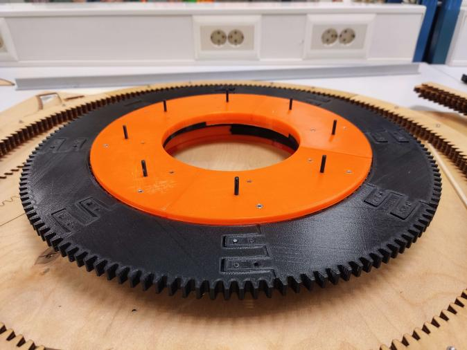
The sun gear is now completely finished. Consisting of the outer teeth ring, upper inner race, lower inner race, and 144 bearing rollers.

The inner race of the slew bearing consists of an upper and lower ring. The seam of these rings is offset by 45 degrees.
After assembling both upper and lower, I realized that I had no way of feeding the bearings into the race.

Therefore I had to bolt the upper plate of the thrust bearing to the lower ring of the inner race.
With these two components now joined, the painstaking process of adding 144 bearings to the race started. Thankfully, I got great help from Ole, as the entire process of cleaning the bearings, and orienting the bearings took nearly an hour.
Thrust Bearing
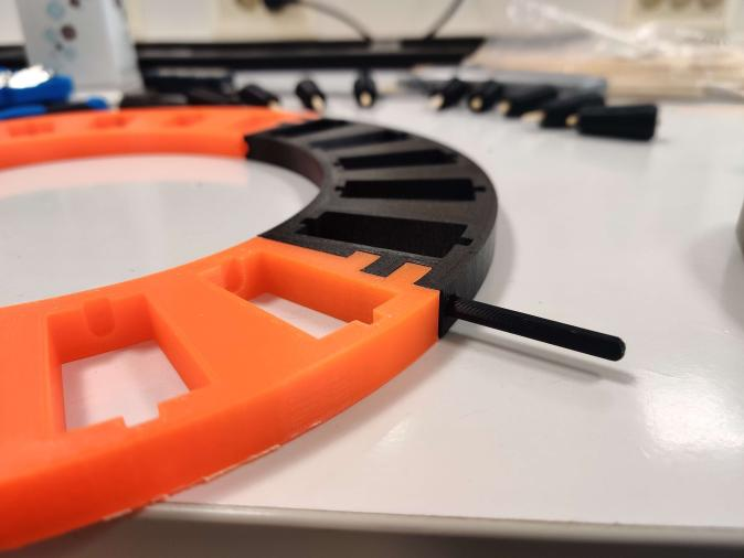
The thrust bearing consists of four segments with matching protrusions/cavities on each end. The segments are held together by pinions.
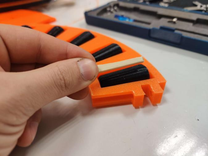
In the first iteration of the bearing/shaft design, said shafts were 3D printed, which obviously -now- was a terrible idea.
Thankfully for Richard Thues endless wisdom, the shafts were replaced with lightly sanded BBQ skewers. This worked remarkably well!
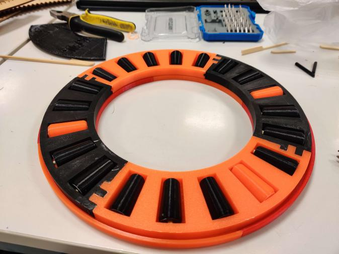
Now the thrust bearing was completely assembled with 20 rollers, 20 shafts, and a bottom plate.

The last step was laying the sun gear on the thrust bearing, and giving it a spin!
The Ring Gear
The Azimuth Drive obviously consists of more than just the sun gear and the thrust bearing. The planet gears had been printed previously, so the only outstanding parts were the ring gear and the mounting plate.

The ring gear would consist of 9 layers of 3.3mm plywood. As with previous parts, the seams of the rings would be 45 degrees offset from each other. 9 layers à 4 segments are 36 pieces.
Of course, the fume extractor for the laser cutter broke, which now has resulted in an incomplete ring gear and missing mounting plate.
Further Work
Hopefully the laser cutter will be up and running again, so that the azimuth drive can be completely assembled. The goal for this week was -and still is- to design the completed pitching system of the paintball marker.