Hi Dronesonen! 😊
This week we have conducted the following efforts:
Discipline – Software:
Erik-Andre Hegna:
This week we focused on setting the MVP together. This means connecting motors and IR sensors to a wooden structure, and using software to push code to the Microbit for motor-movement and sensor-read. This was not as straightforward as we thought, and most of my working hours with the group was to troubleshoot the problems. The problems we encountered was:
- It seemed like the Microbit prioritized power to one motor over the other, so getting them to move in sync was not possible. The motor connected to pin 12 always worked perfectly, while the motor connected to pin 16 always had bugs/did not work.
- The sensor did not work as we intended, and we did not get current through the sensory-circuit at all through-out Monday.
- The motors use quite a lot of watts, and over time the voltage over the battery is reduced. We need to have 3V, or above, over the motor for it to work, and we figured this out after lots of trial and error because we just could not get the motor to work as intended.
As there has been lots of troubleshooting this week, I think we can get the MVP to work as we intend next Monday. Exciting times!
Ask Lindbråten:
Our goal this week was to assemble a low-level MVP. This entailed integrating various subsystems: motors, IR sensors, wheels and Microbit, onto a wooden framework, and make these operate as a whole while seamlessly being able to pass and receive data to/from the computer wirelessly.
I began our session on Wednesday by creating a basic software script that aimed to verify some of our most fundamental A requirements through practical tests on our MVP. This involved stopping, turning, driving forward, reacting to obstacles, aswell as reading and using IR sensor data. The code is cited below:
#include <Arduino.h>
#include <NRF52_Radio_library.h>

int MP1_1 = 12;
int MP1_2 = 8; //motor pin 8.
int MP2_1 = 16;
int MP2_2 = 0;
int IR_receiver = 9;
int IR_emitter = 8; //right side pin 8.
int voltage;
int number;

void setup() {
  // put your setup code here, to run once:
  pinMode(IR_receiver, INPUT);
  pinMode(IR_emitter, OUTPUT);
  pinMode(MP1_1, OUTPUT);
  pinMode(MP1_2, OUTPUT);
  pinMode(MP2_1, OUTPUT);
  pinMode(MP2_2, OUTPUT);
  Serial.begin(115200);
}

void motorControl(int n);
void stop();
void driveForward();
void leftRotate();
void rightRotate();

void loop() {
  digitalWrite(IR_emitter, HIGH);
  voltage = analogRead(IR_receiver)*(1.0/1023); //1.0V for now.
  if (voltage > 0.667){
    Serial.print("Wall incoming!");
    stop();
    delay(500);
    leftRotate();
    delay(500);
    driveForward();
  } else {
    driveForward();
  }
  delay(500);

}

void leftRotate(){
  digitalWrite(MP1_1, HIGH); //accelerate the right wheel motor.
  digitalWrite(MP2_2, HIGH); //Reverse the left wheel or motor.
}
void driveForward(){
  digitalWrite(MP1_1, HIGH); //accelerate both wheels.
  digitalWrite(MP2_1, HIGH);
}
void rightRotate(){
  digitalWrite(MP1_2, HIGH); //Reverse the right wheel.
  digitalWrite(MP2_1, HIGH); //accelerate the left wheel.
}
void stop(){
  digitalWrite(MP1_1, LOW);
  digitalWrite(MP2_1, LOW);
}
void motorControl(int n){
  switch(n){
    case 1:
    driveForward();
    break;
    case 2:
    leftRotate();
    break;
    case 3:
    rightRotate();
    break;
    case 4:
    stop();
    break;
  }
}
However, when it came to running the practical tests, our team ran into some hardware/electrical issues involving the motors and one of the motor-pins on the Microbit that was connected to the MVP. So, while most of the group worked tirelessly to troubleshoot and solve these issues, I decided to join Lars in configuring the wireless communication between the two Microbits we are using.
This proved to be a lot harder than expected, so after a few hours of frustration and troubleshooting, and trying to understand the functionality of the library we had to use and input function-calls with parameters or pointers to struct-objects that included each function the receiving Microbit would use, into the library’s send function – with no luck ☹. We decided to try again the following day. This way we could talk to Steven and receive proper guidance on how to move forward. And it paid off!😊
Steven provided us with the necessary insights to be able to understand the library’s functionality and work out the wireless communication. It’s also worth mentioning that Steven is the one that has developed the library or communication protocols and not us!
The communication protocols work as follows:
- Each Microbit can be set-up as either a sender or a receiver, or both. In our case each Microbit needs to be able to send and receive data (The video below showcases the first two alternatives).
- The parameter you pass through the send function is a pointer to a struct-object that includes parts of a data-packet.
- These data-packets store instructions as a byte in a message or payload array that the receiving Microbit can utilize in order to, for instance, trigger a specific function or action etc.
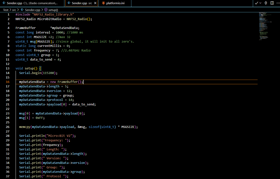
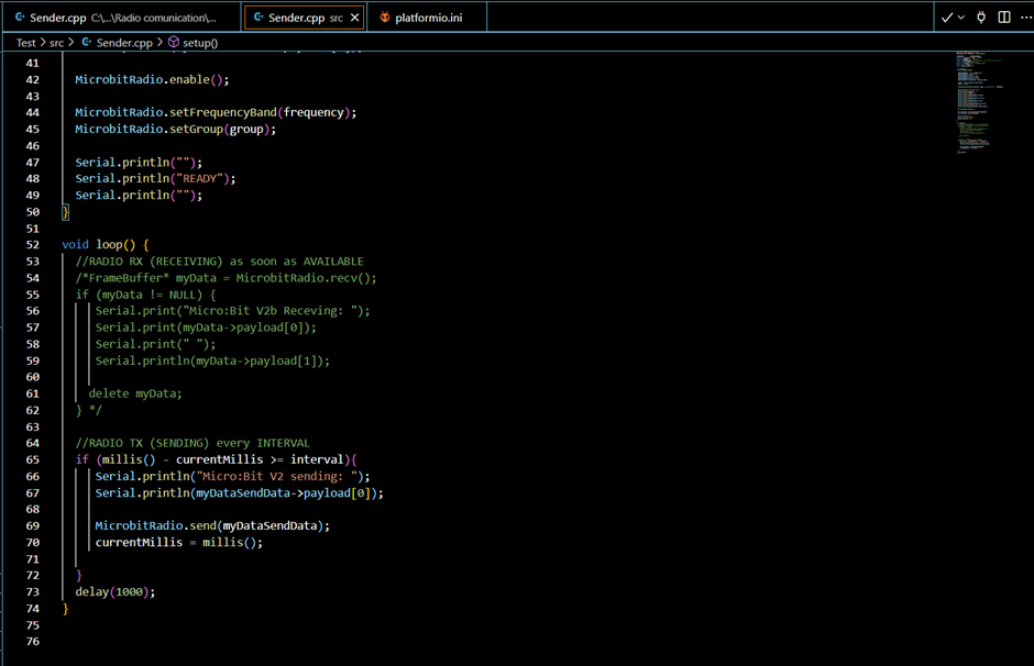
While Lars set up a few lines for the sender script, I set up a few lines for the receiver. Again, most of the software has already been created by Steven. Below is the receiver-script and a video-example that demonstrates the simple transmission of the number 4, as a byte. With this challenge accomplished, we’re hopeful that we’ll be able to complete the practical tests by the end of next week. That’s exciting!
#include <Arduino.h>
#include <NRF52_Radio_library.h>

NRF52_Radio MicrobitRadio = NRF52_Radio();

FrameBuffer *myDataSendData;
const long interval = 1000; //1000 ms
const int MSGSIZE = 2; //max 32
uint8_t msg[MSGSIZE]; //since global, it will init to all zero's.
//static long currentMillis = 0;
const int frequency = 7; //2.407GHz Radio
const uint8_t group = 1;
int ledpin = 10;

void setup() {
  Serial.begin(115200);
  pinMode(ledpin, OUTPUT);
  myDataSendData = new FrameBuffer();
  myDataSendData->length = 5; //3 (fixed) + MSGSIZE
  myDataSendData->version = 12;
  myDataSendData->group = group;
  myDataSendData->protocol = 14;


  msg[0] = 0x00;
  msg[1] = 0xFF;

  memcpy(myDataSendData->payload, &msg, sizeof(uint8_t) * MSGSIZE);

  Serial.println("Micro:Bit V2b");
  Serial.print("Frequency: ");
  Serial.print(frequency);
  Serial.print(" Length: ");
  Serial.print(myDataSendData->length);
  Serial.print(" Version: ");
  Serial.print(myDataSendData->version);
  Serial.print(" Group: ");
  Serial.print(myDataSendData->group);
  Serial.print(" Protocol ");
  Serial.println(myDataSendData->protocol);

  MicrobitRadio.enable();

  MicrobitRadio.setFrequencyBand(frequency);
  MicrobitRadio.setGroup(group);

  Serial.println("");
  Serial.println("READY");
  Serial.println("");
}

void loop() {

  //RADIO RX (RECEIVING) as soon as AVAILABLE
  FrameBuffer* myData = MicrobitRadio.recv();
  if (myData != NULL) {
    Serial.println("Micro:Bit V2b has recieved:");
    Serial.println(myData->payload[0]);

      //Serial.print(" ");
      //Serial.println(myData->payload[1]);

     delete myData;
  }
  }
  /*
  //RADIO TX (SENDING) every INTERVAL
  if (millis() - currentMillis >= interval){
     Serial.println("Micro:Bit V2b sending: 0x00,0xFF");

     MicrobitRadio.send(myDataSendData);
     currentMillis = millis();
  }
  */
Lars Leganger:
This week we finally made a radio connection between two microbits. After we got the second Microbit. Ask and I started by looking at the example codes from Steven. We talked with Steven to get a better understanding of what could be sent and received. After that we found out what we wanted to send based on our needs. We used one of the example codes and modified it so it would send and receive the package we wanted it to send. This is code for the sending Microbit. Most of the code is an example by Steven but with a few changes so we could send what we wanted to send.
A short video of the Microbits sending and receiving:
Discipline – Electrical:
Hugo Valery Mathis Masson-Benoit:
The objective for this week was to connect the Microbit to the electronic system to send and receive data from it. At the beginning I started searching for a way to improve the signal we we’re receiving from the IR receiver. Even if the data was right in the “form”, having the signal between 0 and 1 volt would make it inaccurate. So, I tried to improve the signal to be between 0 and 3 volts. After trying to use a voltage amplifier with a transistor without success, I verified the input of our signal. I was using the static INPUT/OUTPUT of the waveform generator to control our signal. I realized that the input I was using was too low, so I tried with a DC waveform of 3 volts and got a signal output between 0.3 and 3 volts. Despite the little OFFSET in the signal, this output is way more precise than the one we had before.
A video of the signal between 0.3 and 3 volts:
For the MVP design we removed the bypass capacitors to simplify the system at as much as possible. This week I also helped with the test of the MVP by putting the electrical component on a smaller board, and by soldering some wires to connect the motors to the system.
Conclusion for the week:
This week was productive, with the improvement of the signal output and with the connection of the electrical component to the MVP.
Objective for next week:
Make sure to know if everything needed for the project is taken in account for the electrical system, and when it’s done, start the design of the PCB.
Jemima Niquen Tapia:
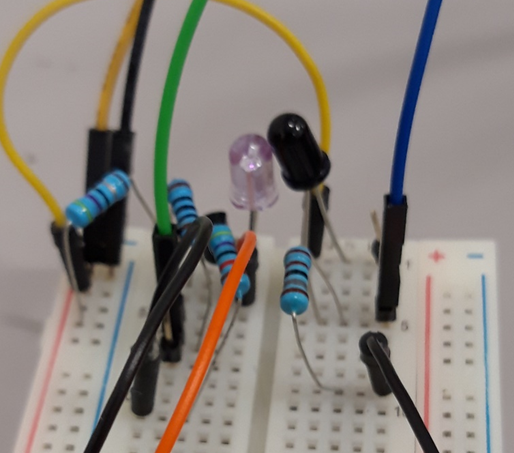
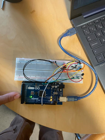
This week in the electrical part we have started doing the MVP prototype, so trying to accomplish all the A requirements. So, we first tried to assemble the sensor with the Microbit, and we found out that we weren’t receiving data and also the motors didn’t really work that well. I first tried to connect the IR sensor circuit to another Microbit as we see in the first picture, and that work, I receive the data of the sensor and we also could turn on/off the sensor, so we discard the problem in the circuit. So, after some tries and suppositions we talk with Steven, he explains us that the problem was that the battery can’t supply enough current, so at the moment we are using an adjustable voltage source, but the next step is to use a more powerful battery but with a Voltage Regulator to have 3.3V at the end.
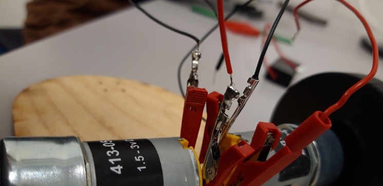
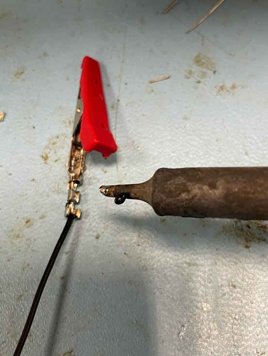
Also, for the MVP we need better connection with the motors, so the electronic partners of the group weld some wires to pegs, as we see in the picture, that way we can have an easy access to the motor’s pin.
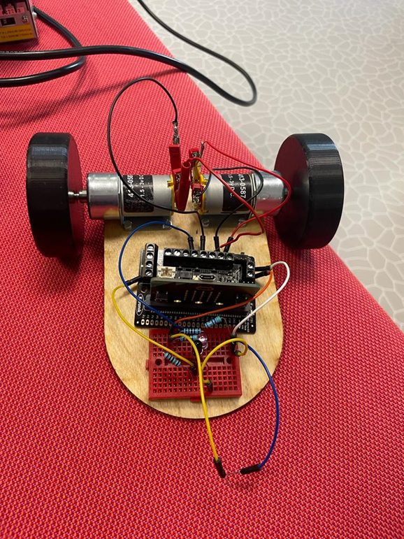
Finally, all look good, the motors work, we receive the data, but we have a final problem. When we did the backward movement, one wheel was not working, we realized that one wheel wasn’t going forward but yes backward. Making tries, we realized that one of the terminals wasn’t working well, so it wasn’t giving high level (1), so in the terminals of the motor were 0 and 0 when we ask for the forward movement. We tried a lot of things to check what could be probably wrong and we didn’t find anything, so we decide to talk again with Steven. After some research Steven finally found the solution, the problem was a bad programing in the library in the software we were using. After that we could construct everything, as we see in the picture, there’s still missing the voltage regulator that will be added this weekend.
Discipline – Mechanical:
Cesia Niquen Tapia:
This week the prototype was assembled, we found the right screws and nuts so that it is well hooked. We did have a problem with the hole of the wheels, it was slightly smaller, but we filed inside with a file in order to make the motors fit.
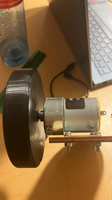
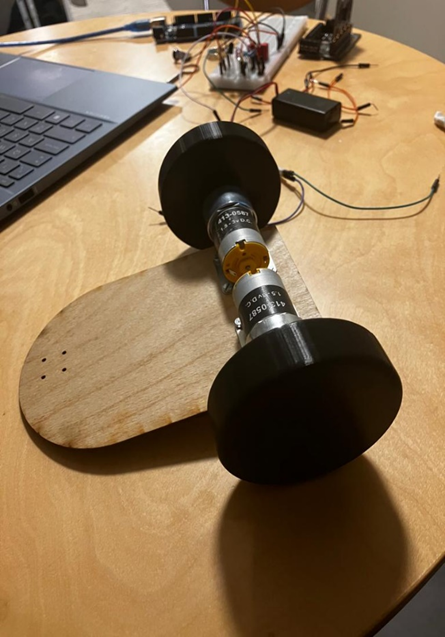
Seeing this first model I can see that the traction on the wheels is not good enough, so thats a change. Also that the wise is way to big for the maze dimensions so it can turn and go without problems.
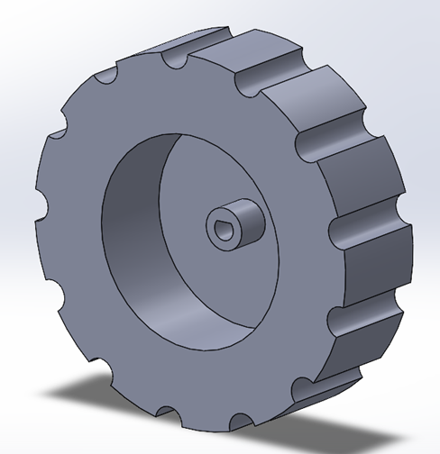
So that also made me think that there is a good part of the motors that it’s just space, so I thought about this kind of wheels. And about the traction I’ve thought about elastic bands or maybe another kind of design.
This concludes our blog post for week 5, see you next week!😊
Best regards,
Group 4