Hi Dronesonen! 😊
Last week, we conducted the following efforts:
Discipline – Software:
Erik-Andre Hegna:
This week was an interesting week as we were supposed to make a simple MVP1. After lecture on monday me and Lars started with exactly that. Our goal was to make the motor turn, stop and reverse on command from a computer. We connected the motor to the microbit, and the microbit to the computer. We then uploaded this code to the microbit:
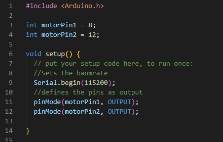

And it worked!
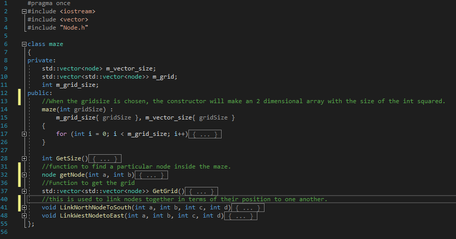
On Wednesday the software part of the group met up to start making some c++ code. We wanted to start developing an algorithm which can map and store data about the maze. By that I mean where the walls are, setting up how the mouse should continue mapping when it encounters multiple ways to go inside the maze, and make a visual representation of the maze. This is what I came up with:
I first made a node class. This is meant to be a representation of one grid in the maze:

Next I made a maze class:
And then the main:
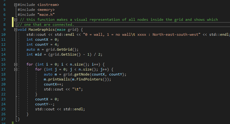

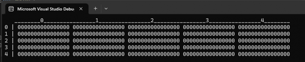
All of this generated this output:

1000 right about “Maze” in “maze is running…” is the (0,0) node.
Ask Lindbråten:
This week I have been working on finalizing option 2 for the early-stage shortest path algorithm from week 3. In summary the idea was to represent the maze as a 5×5 grid with no-walls at this point and only allowing vertical and horizontal movement. In this grid, each cell could store an object that, when combined with other cells or objects, would form a path from a specified start point to the center of the grid. Here is a visual representation of the grid populated with null-pointers before the calculation of shortest path has initiated (the vertical axis represents the x-axis in this case, while the horizontal axis represents the y-axis):
The actual coding of the shortest path algorithm was done using two classes: Node and Maze. Here is the blueprint/class for the node-objects:
#pragma once
#include <iostream>

class Node

{
private:
	std::shared_ptr<Node> m_north_ptr = nullptr;
	std::shared_ptr<Node> m_east_ptr = nullptr;
	std::shared_ptr<Node> m_south_ptr = nullptr;
	std::shared_ptr<Node> m_west_ptr = nullptr;
	bool m_isGoal = false;
	bool m_isVisited = false;
	double m_xidx = 0;
	double m_yidx = 0;
public:
	Node() {};
	Node(double x_idx, double y_idx, bool isGoal, bool isVisited) :
		m_xidx(x_idx), m_yidx(y_idx), m_isGoal(isGoal), m_isVisited(isVisited){}

	std::shared_ptr<Node> getNorthptr() {
		return m_north_ptr;
	}
	std::shared_ptr<Node> getSouthptr() {
		return m_south_ptr;
	}
	std::shared_ptr<Node> getEastptr() {
		return m_east_ptr;
	}
	std::shared_ptr<Node> getWestptr() {
		return m_west_ptr;
	}
	void setNorthptr(std::shared_ptr<Node> n) {
		m_north_ptr = n;
	}
	void setSouthptr(std::shared_ptr<Node> n) {
		m_south_ptr = n;
	}
	void setEastptr(std::shared_ptr<Node> n) {
		m_east_ptr = n;
	}
	void setWestptr(std::shared_ptr<Node> n) {
		m_west_ptr = n;
	}
	bool getIsVisited() {
		return m_isVisited;
	}
	bool getIsGoal() {
		return m_isGoal;
	}
	double getXidx() {
		return m_xidx;
	}
	double getYidx() {
		return m_yidx;
	}
};
In short, objects of this class have a few get and set-functions, variables to store x and y coordinates and pointers to other node-objects in both the ±x, and ±y directions. These are represented through cardinal directions and is used to connect nodes or form paths. The isGoal- and isVisited variables were not used in this algorithm. The Maze class were designed as follows and includes the shortest path algorithm, and a function to connect the created node-objects:
#pragma once
#include <iostream>
#include <vector>
#include "Node.h"
#include <math.h>


class Maze
{
private:
	std::vector<std::vector<std::shared_ptr<Node>>> m_grid;
	double m_grid_size;
	double m_center_cord;
	std::vector<std::shared_ptr<Node>> m_shortest_path_graph;
public:
	Maze(double gridSize) {
		m_grid_size = gridSize;
		m_center_cord = (gridSize - 1) / 2;//odd number grids.
		for (int i{ 0 }; i < gridSize; i++) {
			std::vector<std::shared_ptr<Node>> row;
			for (int j{ 0 }; j < gridSize; j++) {
				row.push_back(nullptr);
			}
			m_grid.push_back(row);
		}
	}
	std::vector<std::vector<std::shared_ptr<Node>>> getGrid() {
		return m_grid;
	}
	double getGridSize() {
		return m_grid_size;
	}
	std::vector<std::shared_ptr<Node>> getShortestPathGraph() {
		return m_shortest_path_graph;
	}

	void calcShortestPath(std::shared_ptr<Node> n) {
		if (n == nullptr || n->getXidx() < 0 || n->getXidx() >= m_grid_size || n->getYidx() < 0 || n->getYidx() >= 			m_grid_size ||(n->getXidx() > m_center_cord && n->getYidx()> 		m_center_cord) || n->getXidx() > m_center_cord ||
		n->getYidx() > m_center_cord) {
			return;
		}
		m_grid[n->getXidx()][n->getYidx()] = n;

		double xidx_next = n->getXidx() + 1;
		double yidx_next = n->getYidx() + 1;


		double xnext_dist = sqrt(std::pow((2 - xidx_next), 2) + std::pow((2 - n->getYidx()), 2));
		double ynext_dist = sqrt(std::pow((2 –
		n->getXidx()), 2) + std::pow((2 - yidx_next), 2));
			if (xnext_dist < ynext_dist || xnext_dist == 				ynext_dist) {								 calcShortestPath(std::make_shared<Node>(xidx_next,n->getYidx(), 0, 0));
			}
			else {
				calcShortestPath(std::make_shared<Node>(n->getXidx(), yidx_next, 0, 0));
			}
		}

	void connectNodes() {
		for (int i{ 0 }; i < m_grid_size; i++) {
			for (int j{ 0 }; j < m_grid_size; j++) {
				if (m_grid[i][j] != nullptr) {
							  		m_shortest_path_graph.push_back(m_grid[i][j]);
				}
			}
		}
		for (int i{ 0 }; i < m_shortest_path_graph.size()-1; i++) {
			if (m_shortest_path_graph[i]->getXidx() + 1 == 				 m_shortest_path_graph[i + 1]->getXidx() && m_shortest_path_graph[i]->getYidx() == m_shortest_path_graph[i+1]->getYidx()) {

   m_shortest_path_graph[i]->setSouthptr(m_shortest_path_graph[i+1]);
   m_shortest_path_graph[i + 1] setNorthptr(m_shortest_path_graph[i]);
			}
			if (m_shortest_path_graph[i]->getYidx() + 1 == 				m_shortest_path_graph[i + 1]->getYidx() &&
m_shortest_path_graph[i]->getXidx() == m_shortest_path_graph[i+1]->getXidx()) {
m_shortest_path_graph[i]->setEastptr(m_shortest_path_graph[i+1]);
m_shortest_path_graph[i + 1]->setWestptr(m_shortest_path_graph[i]);
			}
		}
	}


	void showPointerInfo(std::shared_ptr<Node> n) {
		std::cout << "  (" << n->getXidx() << ", " << n->getYidx() 			<< ") ----> ";
		if (n->getNorthptr() != nullptr) {
			std::cout << "N: (" << n->getNorthptr()->getXidx() 			<< ", " << n->getNorthptr()->getYidx() << ") ";
		}
		else {
			std::cout << "N: " << 0 << ", ";
		}
		if (n->getEastptr() != nullptr) {
			std::cout << "E: (" << n->getEastptr()->getXidx() << 			", " << n->getEastptr()->getYidx() << ") ";
		}
		else {
			std::cout << "E: " << 0 << ", ";
		}
		if (n->getSouthptr() != nullptr) {
			std::cout << "S: (" << n->getSouthptr()->getXidx() 			<< ", " << n->getSouthptr()->getYidx() << ") ";
		}
		else {
			std::cout << "S: " << 0 << ", ";
		}
		if (n->getWestptr() != nullptr) {
			std::cout << "W: (" << n->getWestptr()->getXidx() << 			", " << n->getWestptr()->getYidx() << ") ";
		}
		else {
			std::cout << "W: " << 0 << ", ";
		}
		std::cout << "\n\n";
	}
	void showShortestPath() {
		std::cout << "Active nodes/cells:\n\n";
		for (auto ptr : m_shortest_path_graph) {
			showPointerInfo(ptr);
		}
	}
};
The calcShortestPath()-function can be summarized as follows:
- Check if a set of conditions that could lead to errors or unexpected results is true or false. If true return, if false continue.
- Store the object in the grid-vector on indexes [object->getXidx()] [object->getYidx()].
- Calculate the next x and y values.
- Calculate the distance from the next coordinate, where either x or y has increased, to the center coordinate.
- Call the active function recursively and create a new object, with either the next x- or next y-value, depending on which new coordinate pair is closest to the center. Go back to step one and continue until center has been reached.
After the calcShortestPath-function has run, all you get are a couple of standalone objects mapped to indexes in the grid. However, I also wanted to connect them to form a graph that could be viewed as a traversal path from a start point to the center. With this in mind I created the connectNodes()-function that works as follows:
- Find the objects that are not null-pointers in the grid-vector and add them to the “shortest path graph”-vector.
- Go through every element of the ‘shortest path graph’ vector and check the following: If the x-value of element ‘i’ + 1 is equal to the x-value of element ‘i+1’ and their y-values are the same, we have had an increment on the vertical axis (x-axis). In this case, set the south-pointer of element ‘i’ to point at element ‘i+1,’ and the north-pointer of element ‘i+1’ to point at element ‘i.’ If the y-value of element ‘i’ + 1 is equal to the y-value of element ‘i+1’ and their x-values are the same, we have had an increment on the horizontal axis (y-axis). In this case, set the east-pointer of element ‘i’ to point at element ‘i+1,’ and the west-pointer of element ‘i+1’ to point at element ‘i.’”
To print the graph, I added the showShortestPath()-function and after running it all from main we get the following results (see picture below main()):
 int main()
{
    Maze grid(5);
    grid.calcShortestPath(std::make_shared<Node>());
    std::cout << "   ________";
    for (int i{ 0 }; i < grid.getGridSize(); i++) {
        if (i == 4) {
            std::cout << i << "________";
        }
        else {
            std::cout << i << "________________";
        }
    }
    std::cout << "\n";
    for (int i{ 0 }; i < grid.getGridSize(); i++) {
        std::cout << i << " | ";
        for (int j{ 0 }; j < grid.getGridSize(); j++) {
            if (grid.getGrid()[i][j] != nullptr) {
                std::cout << "     (" << grid.getGrid()[i][j]->getXidx() << ", " << grid.getGrid()[i][j]->getYidx() << ")" << "      ";
            }
            else {
                std::cout << grid.getGrid()[i][j] << " ";
            }
        }
        std::cout << "\n";
    }

    grid.connectNodes();
    grid.showShortestPath();

}
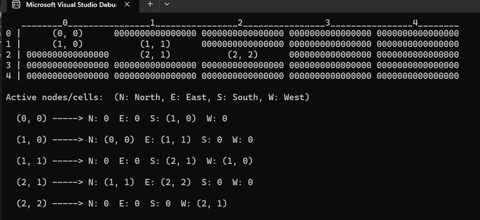
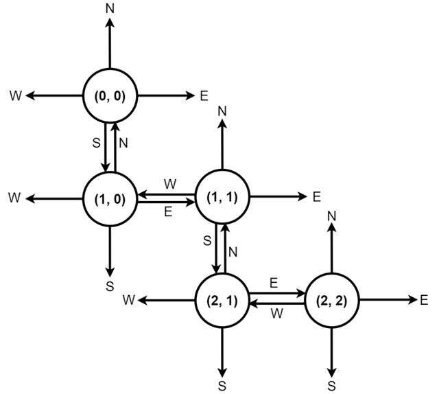
In the printed grid you can see what cells have been populated while the graph below indicates the connections that forms the shortest path. Here’s a visual representation of it:
Potential improvements & challenges:
- Limit the number of necessary turns from start point to center.
- Implement blockages/walls (Combine workings with Erik-Andre’s software work): Remove some cardinal coordinates in each cell?
- Turns and navigation should be based on sensor data in combination with algorithms.
- Transfer code to Visual Studio Code and Platform IO.
- Review and simulate other maze solving algorithms in maze simulators.
- Allow movement and navigation from starting points to center, where the starting points are not elements in [(0,0),(2,2)].
Lars Leganger:
On Monday we tested the code to see if it got the motor to run. The rest of the week i started to work on the radio communication for the Micro mouse and I worked on how each part will communicate with each other.
Discipline – Electrical:
Hugo Valery Mathis Masson-Benoit:
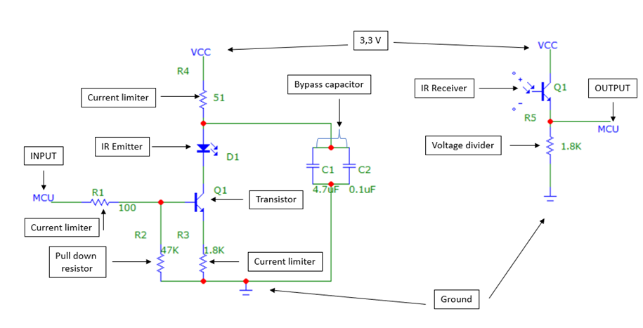
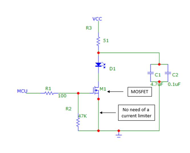
The objective for this week was to find and correct the problems encountered last week on the electrical system. Here is the original design:
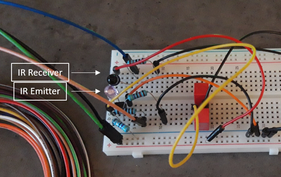
By using the Analog Discovery oscilloscope and with the advice of our teacher, we found that the IR receiver was put in the wrong way on the breadboard. After changing it, we found three things:
- The IR receiver is well receiving the IR light this way.
- A motor can’t be supplied directly after the IR receiver (we’ll use another way to do it).
- With the system in this disposition, the transistor after the IR emitter did not full fill its function, so we couldn’t control the emission.
We tried to modify the disposition of the transistor to make it work, simulated the circuit on Spice, but in the end, we changed the component for a MOSFET, because it’s closer to the function we want to use (as a switch). Here is the new design we got for the emitter part:
After this change, here’s the signal we got with the Analog Discovery (The VCC and MCU are supplied with 3V each):
A video of the simulation:
A video of the system with my finger:
We got the signal we wanted. The signal is oscillating between 0 and 1V. With the advancement of the software team with the communication between the Microbit and the motor, doing the same with the electric system shall be easy.
Conclusion:
The prototype is now working accordingly of what we wanted. We can now do this for the three other sensors we want.
Objective for next week:
Connect the Microbit to the electronic system to send and receive data from it.
Jemima Niquen Tapia:
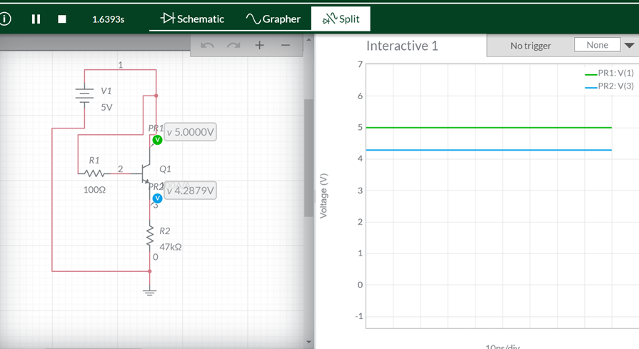
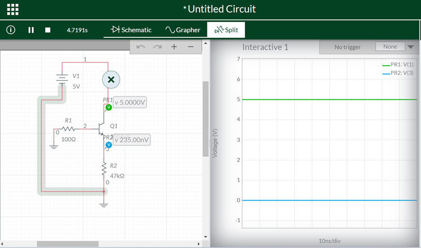
This week in the electrical part we have experienced some troubles. We tried one circuit for the IR transmitter and it didn’t work, so we have to go step by step checking the circuit. We did the little circuit in a simulator to see if everything works well.
As we can see in the pictures, in the two moods the transistor works well, when there was voltage in the base and when there was not as well. We have to point that this was done with an npn transistor, but the original circuit needed a MOSFET. Finally, during different tries, my partner changed the transistor and put a MOSFET instead and it worked.
Also this week I have been trying to figure out how to connect the components in the motor driver board, as we want to put all together next week, and as the datasheet of the board doesn’t said too much, I had to look at other websites.
Discipline – Mechanical:
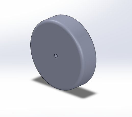
Cesia Niquen Tapia:
This week I’ve met several times with Richard to discuss about the different proptypes or ideas for the different components. So for starting to try all the different parts together we needed some chassis and wheels. For this I needed to take more precise measurements with a caliper, although these measurements may be changed due to trial and error. So we cut with the laser cut a wooden base with space to mount the initial components and the motors. The thickness is 3mm by default. We also print with the 3D printer some basic wheels to detect possible errors and identify the corresponding improvements the micromouse may need to move.
This concludes our blog post for week 4, see you next week!😊
Best regards,
Group 4