This week there have been some more changes. We are now five group members instead of four. These are the group members.
- Ilir Bylykbashi – Software engineer
- John Frederick Lærum – Software engineer
- Thomas Frimann – Mechanical engineer
- Daniels Blomnieks – Mechanical engineer
- Sigurd Sætherø Spangelo – Electronic Engineer
Group weekly reports
Ilir Bylykbashi
Challenges this week:
Creating a working simulation within Unity.
Summary Ilir:
This week John and I worked on the Unity simulation. There are many things to be added and changed in to this project, and it takes a lot of time to do very small things. So far we have made much progress, but in order to have a valid simulation we need to give this more time. This is what I will work on next week.
John Frederick Lærum
Summary John:
This week I continued working on the unity simulation. I’ve been working a lot with Ilir and currently the simulation is a lot of work with small steps at a time in the right direction. The sensing and mapping of walls is slowly getting there as well as the pathfinding logic. The pathfinding logic is perhaps the biggest challenge so far, and even though it’s easy to create an AI pathfinding agent using the Unity Nav Mesh that would cover a lot of what our mouse is supposed to we’re dedicated to creating a simulation that is as realistic as possible.
The first project i worked on crashed when i tried to run it once, after that it kept on freezing whenever we played it. I ended up creating a new project and transferring a lot of the files from the old and created a backup so I wont end up in the same situation again
Thomas Frimann
Monday 11.09.2023
- Meeting and introduced a new member (Electrical).
Tuesday 12.09.2023
Thursday 14.09.2023
- Concept changes due to group modifications (now including electrical), which will provide new opportunities and different requirements.
- Working on the design of wheels/drive wheels.
- Started CAD design of the inner part of the belt to be cast, as well as a concept sketch for the WB (Wheelbase).
- Resolved challenges related to how the belts should be held together and how to design them.
Challenges encountered this week:
Daniels Blomnieks
13.09.23
- 3D modeled micro mouse parts.
- Group meeting with the new group member
- Talked if we can make the motor controller with microbit parallel with each other
- Talken about track design
14.09.23
- 3D modeled micro mouse parts.
Summary
Not much this week. Had a meeting with a new member in the group, electrical engineer. Modeled micro mouse parts for a demo version of micro mouse.
Sigurd Sætherø Spangelo
I have finally caught up on information about the project and joined the MicroMind group. At this point i am now familiar with the project’s goals, framework, and approximately how far the others have gotten during the last 3 weeks.
As an electronics engineer, my role is to be able to link the abstract (software) with the concrete (mechanics). My goal this time around is to be able to take the software engineers out of the simulation and into the real world as quickly as possible, and do the preliminary work needed to get controlled movements in the mechanical system. I’ve first focused on the sensor circuits.
There are three things we want to sense (as we are aware of, so far). Each necessary sense has a couple of different ideas that have been considered so far to implement them. If necessary, in some cases multiple solutions can be combined to achieve better accuracy. The senses and concepts are listed below, sorted by priority:
1. Distance from walls
– IR-sensors (LED + phototransistor)
2. Wheel axis rotation
– Orthogonal Hall-sensor pair and rotating magnet on axle
– Encoder (plate + optical sensor)
3. Orientation (compass)
– On-board compass with MCU
– Using movement data (accelerometer/motor throttle/etc.) to estimate displacement from original rotation
– Image-processing/recognition + down-facing camera on a pole
My first task was to become somewhat familiar with a couple of components looking at their datasheet (SS49E, KY-024, KY-010, 413-0587, 5698) so i can later make informed design-decisions for sensing and motor-control.
I have, since wednesday, been working on an early prototype for the distance-sensor, following the IR-sensor concept. This circuit has been put together on bread-board, then tested and optimized, with the final result only consisting of 4 parts in total.
The concept i have finally arrived on is shown below (without multiplexing):
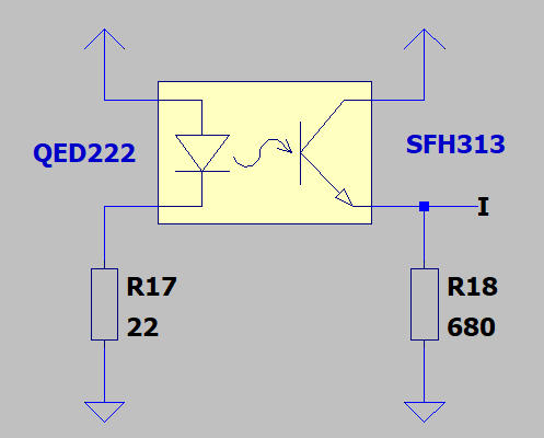
During testing, this circuit performed quite well, being able to detect objects as far away as 14cm from the bulb (with bulb pointing directly towards object).
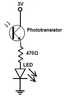
The circuit was designed based on this simple phototransistor-based dimmer circuit shown below, but with the indicator light removed and the load resistance adjusted to provide a signal that is optimal for the microcontroller’s analog-in voltage range (assumed to be ca. Vf to Vcc – Vf = 0.6V to 2.4V):
During development, i filmed a short video showing a working intermediate version of the sensor, where the LED has still not been removed yet, lighting up whenever objects get close to the sensor:
With the last, indicator-bulb-less, 4-component design, we get a signal-range of ca. 1V-2V. However, please note that both the IR-LED and the IR-phototransistor are temporary substitutes for the parts that we planned to use (QED222 and SFH313). The IR-LED i’ve used is SFH409 and the phototransistors are unlabeled. It’s possible that the resistor values can, or will have to change, if these originally intended components are to be used instead. For instance, QED222 has a much higher power-rating than SFH409.
The design was thereafter made multiplexable. I’ve acheived this by connecting all emitters together, sharing the same load, while a BJT is used to switch the power for each sensor seperately. To remove unwanted transients when switching, i have also added a 1. order filter to the output. It’s critical that only one sensor is enabled at a time. This circuit using 2 sensors, is shown below:
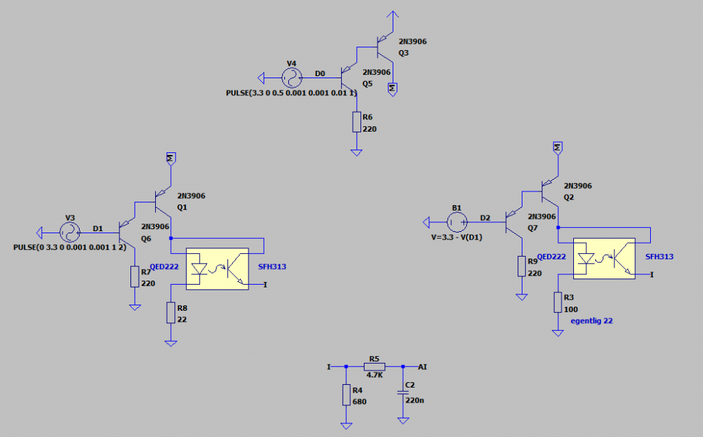
This concept for IR-sensor multiplexing is highly scaleable, where the count of analog pins used are always 1, and the count of digital pins used are ceil(log2(N)) + 1, for N sensors, given that a binary encoder is used. Without the binary encoder we get N + 1 digital pins instead.
It should be possible to switch the sensors on using short pulses. With the current transient filter, the pulse-width for the “enable”-signal cannot be less than 10ms, or it will lead to an inaccurate measurement. Using short pulses will use less overall energy, and also allow for more power output from the IR-LED’s.
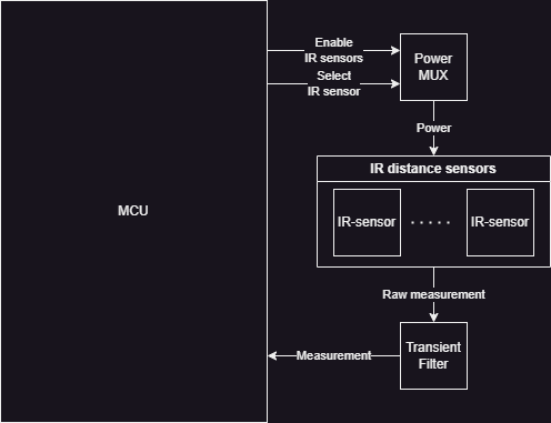
Then, finally, i drew a diagram to show an abstract overview of the electrical system for the distance sensing: