Hi Dronesonen! 😊
This week we have been splitting up into our own disciplines and conducted the following efforts:
Discipline – Software:
Erik-Andre Hegna:
I tried to get a grasp on how we could implement Djikstras algorithm into the micromouse as a way to store, understand and adapt information about the maze. This included sketches, discussions and programming.
Ask Lindbråten:
I worked with Erik-Andre on how we could implement an efficient but early-stage mapping and run mode algorithm for the final software to build upon. We discussed and sketched until we came up with an idea where the maze is represented as a 5×5 grid with 25 total cells or nodes. The grid is implemented through utilizing a 2D vector, or a vector of vectors with node-objects or pointers to node-objects.
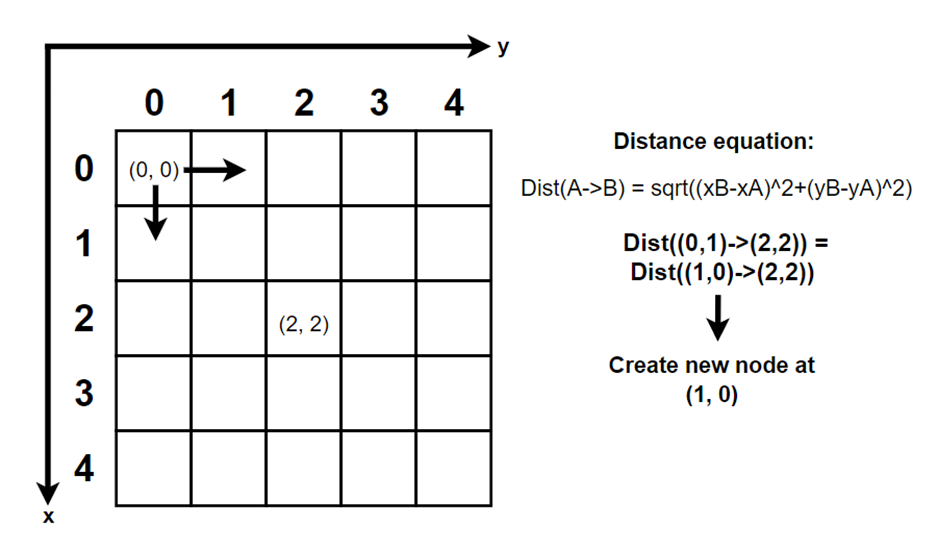
Each cell has two indexes: The first one represents the row-vector the cell/node belongs to and the second indicates the cell’s position within that row. The idea is that these two indexes represent a set of (x, y)-coordinates, that can be used to map the entire maze and in calculating the shortest path from the active cell to grid centre (which would be the goal-cell for the micromouse).
Calculating the shortest path can be accomplished using various methods, but we have discussed two specific approaches: 1: Counting the number of nodes or cells created to reach the center cell -> (3, 3) from the starting position -> (0, 0) during search mode. We then pass the path with the fewest nodes visited to the run mode. 2: Comparing the absolute value of the next cell/node’s coordinates to the absolute value of grid-centre coordinates, and continuously create the next cell/node that is at the least distance from the grid-centre. In case the calculated absolute values are similar in comparison to the absolute value of the cell center, we have discussed the possibility of setting a condition that the right-most node would always be created, but we haven’t completely decided yet. For the time being we are planning to implement the option 2. The picture below should provide a clearer visual representation of how this could be done:
Lars Leganger:
This week I’ve worked with the Bluetooth function on the Microbit. I’ve tried to make it receive and send data between the Microbit and my computer.
Discipline – Electrical:
Hugo Valery Mathis Masson-Benoit:
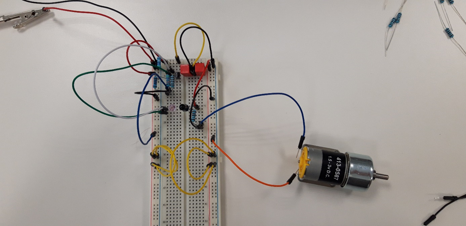
For the electrical part, this week was dedicated to the creation of the first prototype of the Micromouse. The objective was to put all together on a breadboard the components of the two essential parts: the sensors (IR emitter / receiver), and the motors to test everything. To do this I got all the components needed for one sensor and a motor.
Components overview:
- Transistor (BC141)
- DC voltage supplier
- Multimeter
- Capacitor:
- 2 of 4.7uF
- Resistor:
- 1 of 50 Ohms
- 1 of 100 Ohms
- 1 of 47k Ohms
- 1 of 1.8K Ohms
Picture and video of the prototype:
Conclusion for the week:
The basic prototype is working. When observed with a multimeter, the IR emitter and receiver have the right values, and the motor is turning. The only problem is that I had difficulties to make the IR emitter and receiver communicate. That’s something I need to work on for the future tests.
Objective for next week:
Connect the Microbit to the prototype, and make it control it with a simple script.
Jemima Niquen Tapia:
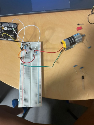
This week I have been focused on trying to control the motor without using encoders for our first design, so I have been investigating the possibility of using a control PWM for the motors, also seeing the advantages and the disadvantages of it, and also having in mind that it’s just momentary. The idea is to do the first try with an Arduino Mega, and check what to improve.
This week also a meeting for try the IR sensors has been done, as we already know how to do the circuits. Looks like the circuit wasn’t working, so I decided to do the simplest circuit (as we see in the picture) and try to see which is the problem. The circuit is composed by the transmitter powered by 3.3 V and a resistor. For the receiver we have a voltage divider and connected in the middle the motor, which it is supposed to move except when there is no connection between the transmitter and the receiver. Unfortunately, this does not work, so we have to ask to the teacher.
Discipline – Mechanical:
Cesia Niquen Tapia:
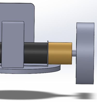
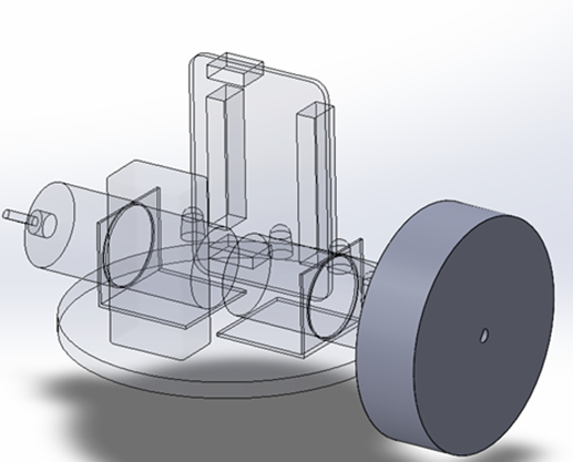
This week I’ve been trying to keep looking at the reasons for the difference between the most typical models. Since we still don’t have a component needed list, I tried to design another kind of model with another distribution.
Also, I tried to do a pre-design for the wheels. We have heavy components and keeping in mind the maze dimensions as a first design I’ve set 5 cm in diameter and 2 cm wide. Also, I think that the PLA material that it’s easy to use and pretty much rigid. I’ve checked with the teacher, and we do have it available in the university. I’m thinking about for tread design because a simple wheel would be a smooth, flat surface on the wheel without a grip pattern design and, in terms of ease of manufacturing, there are less complications in 3D printing. And as the maze it’s supposed to be predictable and at the beginning our priority is not to be fast, we can set this first prototype.
This concludes our blog post for week 3, see you next Sunday!😊
Best regards,
Group 4