Welcome to our blog post for the third week of our Turret system project. Below, you will find the contributions made by each of our team members:
Harald Berzinis
Introduction:
Building a turret that can automatically target balloons based on camera input can be a challenging problem. This week I have made a code for motor control. The turret can be controlled manually with a joystick or automatically by reading the target’s position from a camera feed.
Functionality Overview:
Initial Setup:
The code initializes the Raspberry Pi’s GPIO to control the motors and read inputs from a joystick. It defines pins for the joystick axes, a button for switching between manual and automatic modes, and pins for the two stepper motors that move the turret.
PID Controller:
The code introduces a PID (Proportional, Integral, Derivative) class. The PID control algorithm is designed to bring the turret’s direction error to zero, i.e., perfectly aligning it with the target. The three components (P, I, D) determine how the turret responds based on the current error, the accumulation of past errors, and the rate at which the error is changing, respectively.
Targeting Mechanism:
The script assumes a camera resolution of 640×480 pixels and uses the center (320, 240) as a reference. This will probably change due to the choice of the camera module. The target’s position is read from a text file named ‘target_position.txt.’ If the file doesn’t exist or contains invalid data, the code defaults the target to the center of the camera feed.
Motor Control:
The control_motor function directs the motor to move based on the PID output. It limits the step counts between 1 and 10 for safety and smoothness, determines the direction based on whether the output is positive or negative, and then pulses the stepper motor to move it.
Operational Modes:
Manual Mode: Activated when a button is pressed. The turret is controlled by the joystick, and the aim is to bring the target (balloon) to the center of the camera feed.
Automatic Mode: Activated when the button isn’t pressed. The turret automatically moves based on the target’s position as detected by the camera feed, trying to keep the balloon centered.
Safe Exit:
The code includes a mechanism to clean up GPIO configurations if the script is interrupted, ensuring the pins aren’t left in an undefined state.
Conclusion:
The fusion of a PID controller with camera input and motor control offers a sophisticated and precise mechanism to target balloons.
Next week:
Further testing of the code.
Mats Bergum
While trying to simulate the circuit made by Harald, I found that some of the components had to be changed. The voltage regulator (LM317D2TR4G) was not in stock, and the PMOS (BS250FTA) did not have a spice file connected to it. Also the zener diode (TZMC13-GS08) may not meet the requirements for this circuit. Moreover, it proved more challenging to simulate the circuit than initially thought. So something I have to continue next week.
I have also been making a library in OrCAD Capture for the 3.3V to 5V converter with all the necessary symbols.
I watched some OrCAD and Cadence Allegro PCB Editor tutorials, mainly from Robert Feranec. I recommended the following video to learn the basics. https://youtu.be/d_TPIxPX01s?si=QUAzUiZ7sdZBYiMq. This video taught me how to make footprints and 3D models for components and use them to design a personal printed circuit board (PCB).
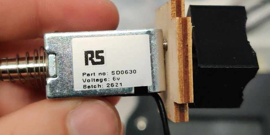
Steven came with a 6 V linear solenoid (SD0630). I had no time this week to test the component and verify its usability. So next week, I will test the trigger resistance of the paintball gun and if the solenoid provided is suitable. Moreover, when I looked for the datasheet for the solenoid, I only found one with a supply voltage of 12V with the part number SD0630. However, the datasheet for SD0629 matches the component we got from Steven. This is something I need to look into as well.
Christopher Daffinrud
YOLO and Tensorflow for Object Detection:
We began the week by continuing our research into object detection modules in Python, picking up where we had left off. We explored both Tiny-YOLO and Tensorflow Lite. Among these options, Tiny-YOLO and the YOLO model in general appear to be the most suitable due to their user-friendliness.
One topic of discussion was the absence of a pre-trained model for detecting balloon objects. Creating a model from scratch was considered potentially too time-consuming.
Raspberry Pi Display GUI
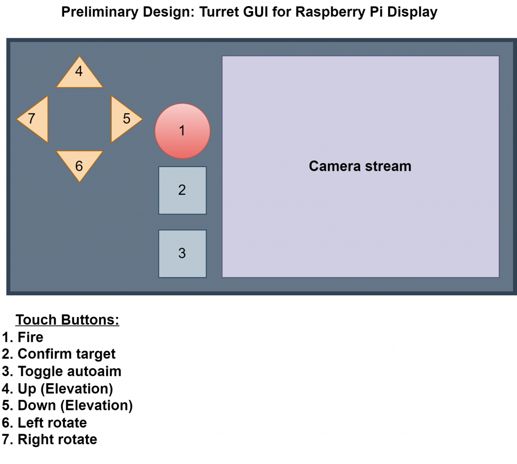
As specified in our requirements, we aim to have a Graphical User Interface (GUI) displayed on a Raspberry Pi Display. Tkinter could serve as a viable GUI framework for Python, depending on the available resources.
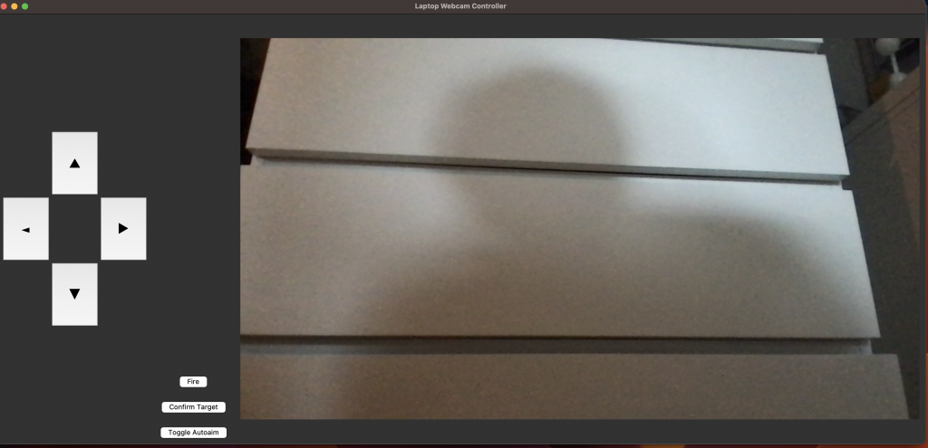
I sketched a diagram based on our GUI requirements (1) and also implemented a preliminary example (2) for our GUI in accordance with this diagram.
Ole Eirik Solberg Seljordslia
This week has been used to further investigate Yolo’s runtime performance on the Raspberry Pi while processing real-time video. I’ve tried run different versions of the models with altering amount of pixels to process.
Running the v8 model on the Pi resulted to about 1 frame being processed every 10 seconds, this was while utilizing 4 cores to process. The best result was achieved by setting the video resolution to 64×96 pixels, this resulted in about 10 fps. But processing so few pixels greatly decreased the precision of the model. So this was an unacceptable solution for our team.
We therefore investigated the possibility of moving the processing to different hardware. We were lucky enough to get our hands on the Intel® Neural Compute Stick 2 (Intel® NCS2).
I spent the remainder of the week trying to install the OpenVino dependency to support runtime of the Compute Stick.
This was a tiresome job since the support and installation on the Raspberry Pi 4 was poorly documented. I eventually managed to install an older compatible version of OpenVino on the Pi.
The goal for next week is to run code on the Compute Stick and test if we can use the Yolo model.
Hannes Weigel
This week I continued working on the azimuth rotation, and additionally made a draft for the pith rotation.
Azimuth Drive
I calculated the optimum ratio for Sun:Planet:Ring which had to to be a multiple of 3 as we aim for 3 planet gears. With the initial target ratio of 1:8 this lead to a 144:24:192 ratio.
The next challenge was to support the sun- and planet gears.
In turret designs, usually the ring gear is a long bearing rail, which in this case wouldn’t suffice, as we want the motors to drive the planet gears. Therefore the entire mounting plate for the motors would have to be suspended on an shaft running through the sun gear.
As the sun gear needs to move independently from the planet gears, the would have to be a bearing between the shaft and the sun gear. For stability sake, the shaft would need to be as big as possible, and thereby the bearing. This would exponentially increase the cost of the system.
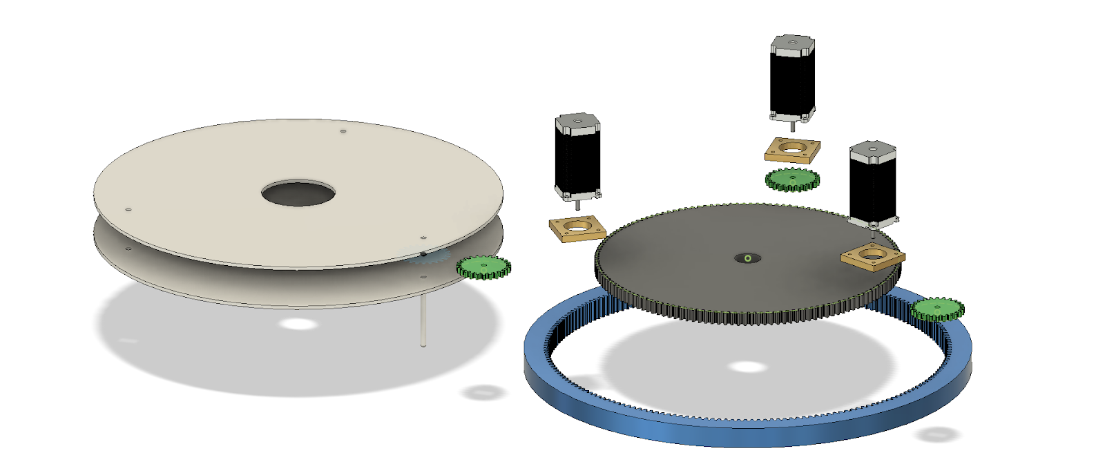
The solution was to adapt a 3D printable slew bearing.
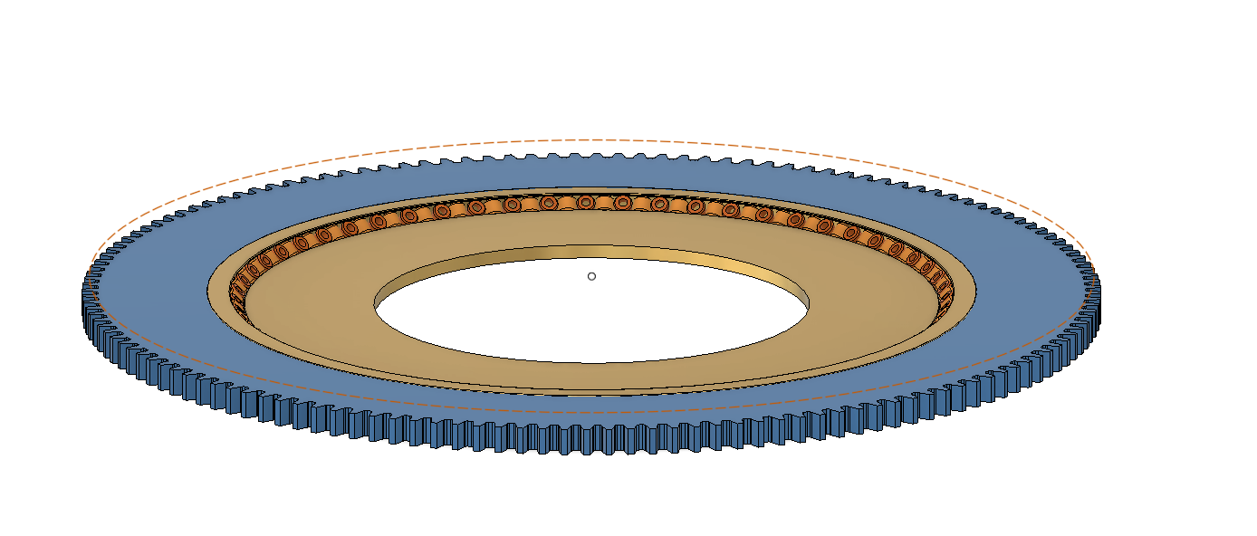
Now the sun gear would consist of an outer ring with teeth, and an inner part housing a slew bearing.


Now we would be able to suspend the sun gear, allowing the teeth to rotate freely as the top plate (housing the paintball marker, stepper motors, and other components) would rotate freely as well.
Pitch Drive
As mentioned in the previous week, the step-distance of the stepper motors (17 and 23) is sub-optimal.
Therefore the pitch would be controlled by a stepper motor driving a trapezoidal rod.
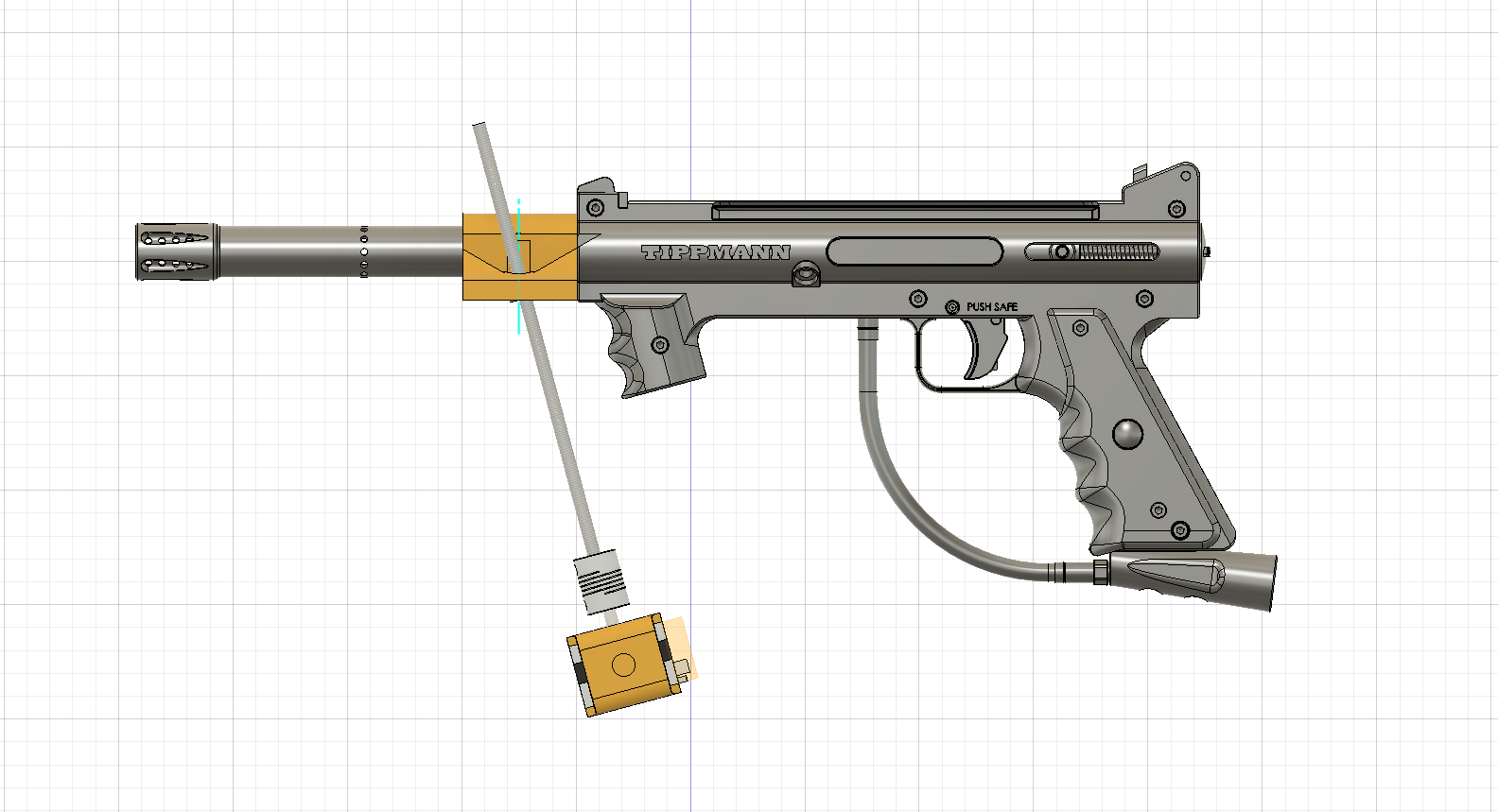
Please note that this is not the actual model of the paintball marker. I did not take the time to generate an accurate model, as the solution should be independent of the marker.
When the motor screws the threaded rod in such a way that the marker is pushed upwards, the nut resting on the rod and the motor would want to pivot.
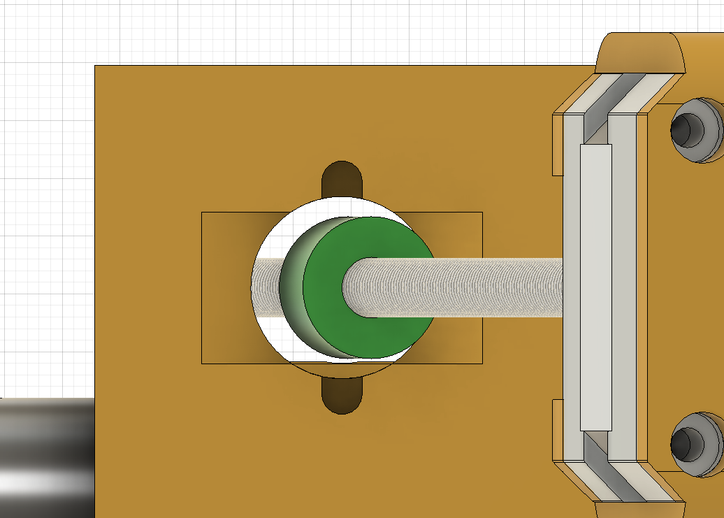
Here the nut is in green as we view the assembly from below.

So that the nut and motor would be able to pivot, the nut and motor mount would feature small protrusions on which they would pivot.

Additionally -even though not modeled yet- the paintball marker will pivot on an axis placed at the center of mass of the assembly.
Stepper Motors
The stepper motors used for the azimuth feature a smooth shaft, which introduces a problem with mounting the gears to the shaft. Traditionally this is achieved with friction mounting set-screws on the axle, but this solution is sub-par.
Therefore the decision was made to CNC down the shaft such that it would become a D profile.


Further Work
Most of the design process is finished in this stage and needs to be tested against our production methods. The goal for the week is to produce a prototype of the azimuth- and pitch rotation.