Game environment
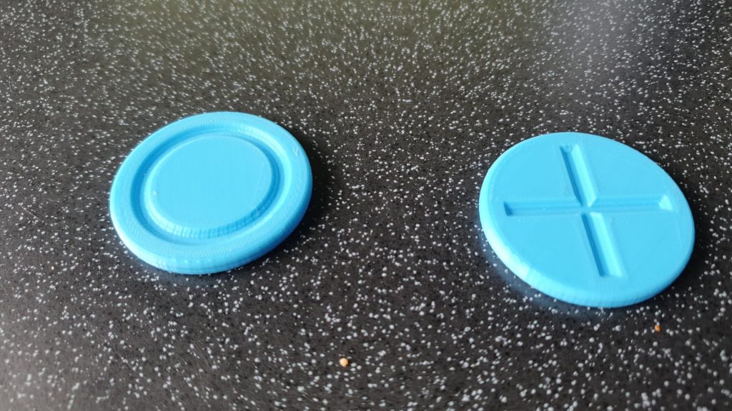
Victor had the first prototype of the gametokens had been printed to see if the tolerances are good to fit the inlay in the token. The tolerance was chosen too small, so the dimensions were adjusted and the inlay was reprinted. The fitment was much better and a second version of the main token in the final color was commissioned to go on with the visual recognition.

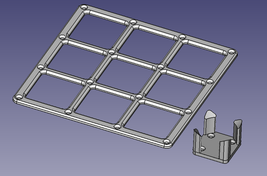
Also Victor went on with designing the gamefield and the tokenstack which will be fitted on a solid baseplate with the arm itself. To ease the use the gamefield will be a one part frame in a different color to the baseplate, so the tokens have a defined area where to lay and can be easily seperated by contrast.

Object detection using a Raspberry Pi
This week, Ole Christian started the installation of an object detecting software on a Raspberry Pi. I started the task by installing the operating system “Raspbian Buster” on the Raspberry Pi 3 Model B+. I also installed the Raspberry Pi Camera Module. After setup, I updated the Pi and followed the Tensor Flow Lite tutorial by “Edje Electronics” on YouTube (Link: https://www.youtube.com/watch?v=aimSGOAUI8Y). The installation process ran mostly without trouble, but still took some hours (mostly due to loading and downloading).
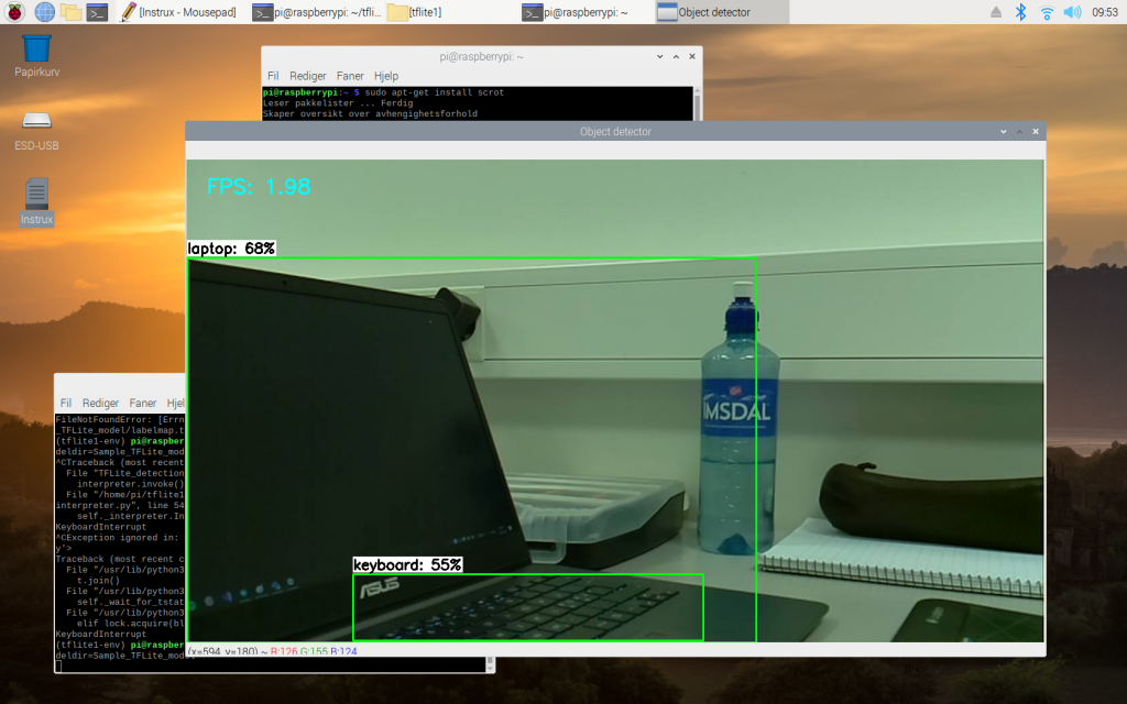
I ran the example code provided by the tutorial, with the “COCO SSD Mobilenet Sample Model”. This is a pre-trained object-detection model by Google that are converted to work with TensorFlow Lite. After some error fixing and troubleshooting, I finally got it to work.

You can see boxes around recognized objects, a label of what has been detected, and the confidence level in percent. The model I am using can recognize 80 common objects. It is not perfect and will yield many false positives. The minimum confidence level is 50%. I can increase this to get less but more reliable detections. This software is running at ~2 fps on the Raspberry Pi 3.
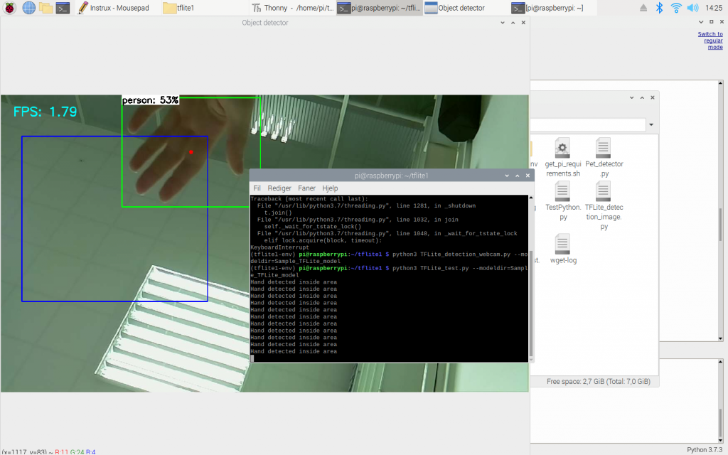
I started to experiment with the code and wanted to add a detection area. The code will first check if the object I am looking for is detected. If it is detected, it will check if the object is inside the chosen area. If it is inside the detection box, it will print a message to the terminal. I also added, a visual square which is the same size as the detection area, a dot at the center of detected objects, and preview-window resizing.

The model will recognize my hand as a person because the model is trained at “whole” people. It thinks a detected hand probably means a person is present in the video stream. Although, it is only 53% confident. When the center of the “person” is inside the detection box, a message is printed.
Next week I will try to:
- Create at least 9 detection boxes (for tic-tac-toe)
- A timer to make sure objects is reported as detected after a certain time has passed (for piece placement on the play field)
- Detection of our game pieces (“X” & “O”). This will might require a model that I train myself or a model that is trained on letters.
- Communication between a Raspberry Pi and Arduino
Machine
Frustrating week with scrambling my design 4 times. Due to new problems occurring as I “finished”. Placement of servos and how the whole thing would be put together. I asked Richard to print some parts for size fitting. According to my previous discoveries, the prints had an adding of 0,2mm of material pr surface. So, I made some new test part that had a hole with a specific diameter and plugs that where 0,4mm smaller in diameter than the hole. The hole was 8mm and the plugs where 7,5-7,6 and 7,7mm diameter. The 7,5 fitted the best. With the 7,6 being tight fit. I also got some part that I got printed just to have a relation to fillets and M bolts.
I got an ide that i wanted to see if we could cover the arm with a blanket of plastic that we could praypaint. so i also I got an idea that I wanted to see if we could cover the arm with a blanket of plastic that we could spray paint. So I also got a sample of 0,5 mm plastic sheet. And it looks really good :).
I decided that I needed to start with a realistic part. So, I made the first part where the first servo is to go. Taking into consideration the 0,2mm rule I found. Plus, I wanted to see if I could use the 2mm wheel bearing. I made a small scale of the part where this will be used. Lastly, I also made a fastening tool that I wanted to test.
Waiting for this print and if one of my teachers have found the original part for the servo. This will decide if I need to design new fastening to the servo or just an add on. Not so much to report right now. I did so many designs just over and over again.