Software functionality, servos and game piece detection
This week, Ole Christian focused on which functions the arm should have, Tic-Tac-Toe piece placement detection, what needs to be programmed and some more servo testing.
I preformed the same servo test as I did in the last blog post, but this time I also added a power supply to the circuit. This eliminated the servo “jitter” I had problems with before.
The current planed robot functions are drawn in a use case diagram.
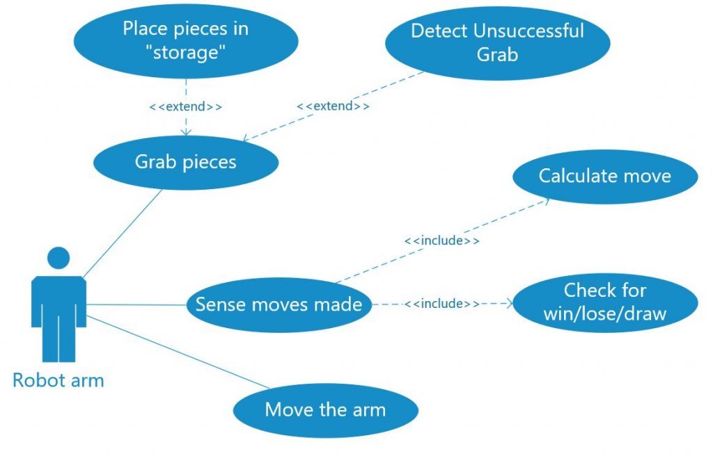
I thought about what needs to be programmed and worked on in the next weeks.
- Robot arm movement and grabbing
- The Tic-Tac-Toe game
- An opponent to play against
- Detection of game pieces and moves made
- Communication between a Raspberry Pi and an Arduino (If we decide to use camera detection)
The robot must detect where a player places a piece and what piece are placed in order to play. We talked to each other in the group and came up with multiple solutions. Some of them are switches, photo resistors, weight measurement and camera detection.

The use of switches or photoresistors is something I know I “could” implement. But it would require at least 18 more components and add a lot of wires. I decided to see if I could use a camera to detect the pieces instead. This is something I have very little knowledge about and are not certain if I could make work. Next week I will see if this is possible. I will look into using a Raspberry Pi with a camera module and an object detecting software.
Construction
The task responsibility of construction was transfered from Victor to Joakim, due to better knowledge in mechanical engineering.
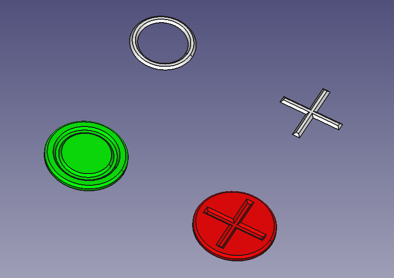
So Victor now takes care of the main project management and some other needed construction beside. He created a first approximate project time plan and started with the modeling of the gamefield and the gametokens.
Tic Tac Toe Implementation
This Week, Mahamed started implementing the code for the game, almost done 75% of the code, still some work to do with the robot arm part. by the end of next week, I hope am done with implementing the code for the robot arm parts.
Machine
So, Joakim started the design for the arm. Starting with the base i first meant to use a wheel bearing, but i went away from this idea since i wanted to be able to have a wider base. I wide base would mean more stability if we later wanted to explore other options for our arm. I have also decided to use most PLA for the production. this since PLA i fairly strong and it makes modelling much easier.
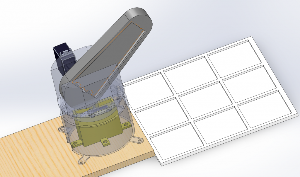
As now the arm is just drawn for function. like where to place the servos and how to get a bigger rotation plate in the base. Im also trying to think further to other things that gives my pieces more function. Like how i added some wholes to the arm so that we maybe could find some ways to fasten cables in a smart way. further down the line I will clean up the model for the estetics. I do have some ideas that i want to explore but for now they needs a little more testing of PLA.

I also did not have any experience working with plastic. so i asked Richard to print me some examples so i could look at accuracy, the surface, fillets and general strength of different thicknesses.
The pieces told me many things. I also just for fun ran a strength simulation on one part. Finding the tensile strength of PLA on google and using a Plastic material in solidworks with the same strength. the result was good. not accurate but far from the possibility of fracture in the material.
if i where to give one advice for the next ones doing a project like this. Buy a caliper! and sketch everything on paper so that you keep track on realistic size of you parts.
the Fun/struggle is marching on.