Electronics
For the main control processor involved in the project, a microcontroller was picked, that is capable enough to process many processes simultaneous as well as do some floating point calculations if necessary. Here, over-sizing was preferred instead of meeting the requirements now known. You never know what the µC should be capable of later in the project…
A STM32F411 was chosen, because it is waaaayyyyy easier to debug than e.g. a Arduino. Furthermore it is programmable in a great IDE called STM32CubeIDE and because it features a moderately modern Cortex M4 processor with a floating point unit as well as many communication interfaces like SDIO for SD-Card interface, I2C and SPI for communicating with other chips and sensors, a fast 12 bit ADC with 16 channels and USB on-the-go capability to interface with e.g. a laptop to transfer data at a high rate.
The µC is available on a small form factor board called ‘BlackPill’ from the manufacturer / designer WeAct Studio.
The microcontroller will be programmed primarily in C with implementation of the FreeRTOS real time operating system to make processing different tasks simultaneous easier and more predictable.
Solenoid Control
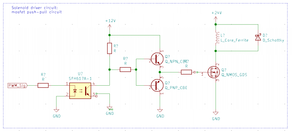
To control the solenoids, a schematic was sketched out to control a MOSFET with adequate speed, as the power losses in a MOSFET are primarily related to the on- and off-switching speed. For this purpose and because the µC only outputs voltage level as high as 3.3V, a circuit with BJTs was chosen. To prevent cross-talk from the power-circuit to the microcontroller power supply, the signal should be galvanic separated using optocouplers.
The circuit chosen is called ‘push-pull gate driver’, if a MOSFET with a high Gate-Source-Voltage for full conduction is available. If it is also feasible to drive the MOSFET with a lower voltage than 10V, a simpler circuit will be considered
Source: Toshiba Application Note: MOSFET Gate Drive Circuit
Ball Detection
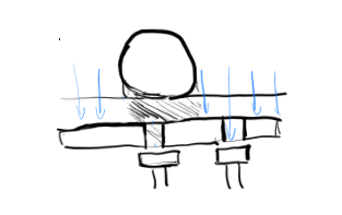
As for detecting the ball coming close to the flippers is a key element in the autonomous flipper machine and using a camera for this purpose was not wanted, other methods were evaluated. One method consists of having light sensors below the surface of the board and by detecting the difference in light conditions through small holes when a ball rolls over, it can be detected and tracked. To achieve this, the board has to be made up of at least a layer with small holes in a pattern and a certain distance with light sensors below these. The light sensor can be made using Light Dependent Resistors (LDR), which are basically semiconductors with high electrical resistance. When light hits the surface, the photons transfer some of their energy to the electrons of the semiconductors, which break free from their atoms and thus increase the conductivity [electronics notes] .
As for now, only first sketches were made of how to scan all the sensor, bei either using many ATMega to handle > 100 sensors, or to create a matrix which will be scanned continuous and thus reduce the required pins.
Also no decision were made so far if the sensors should be evaluated with their analog signal (resistance) or by abstracting and defining a threshold on when the sensor is read as active.
The disadvantage of transferring the information to binary is first of all the loss in information, as the position of the ball could in worst case not be tracked through the entire matrix but only a few sensors where it passes over directly. Furthermore adjusting for different light conditions and so calibrating is barely possible, as the threshold is implemented in hardware instead of software, when handling the data in analog format with a ADC.
But sampling many pins with a ADC of e.g. the Arduino is slow as the ADC conversion takes some time and only a single ADC is present in many ATMega Cores. Furthermore to get a reliable result, more than one sample should be taken as it is known that the first samples may not represent the actual value on the input.
For the Sensors, the idea of designing separate PCBs which only contain the sensors and maybe its evaluation unit (ADC or Comparator) was proposed, which would reduce the cable required to wire all sensors and also may reduce the probability of wiring errors and other errors associated with wiring lots of components.
Software
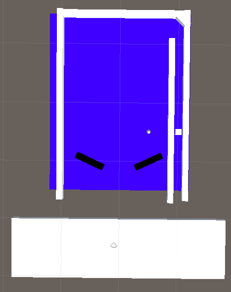
The Unity simulation is now up and running to an acceptable degree. It allows the group a testing arena for the project and a space where some ideas can be ran. Among the ideas tested so far were:
- The idea of not using a ball, but a slippery, flat surface instead.
- The possibility of a cube.
- Simple angle calculations.
All of this allows us to diregard or reinforce certain ideas by using “practical” examples.
Discussions were had as to the capability of the processor and whether or not a simple arduino would be enough to handle the calculations keeping the system running. As of now, the Arduino UNO we have access to, has 16mHz to go on allowing some “wiggle-room” when considering how much information it can handle.
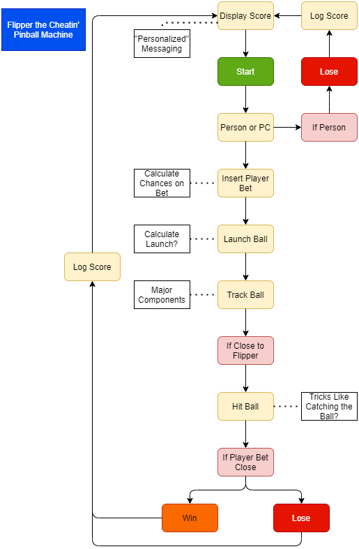
Some code charts have been made in the meanwhile, simply dealing with the functions that has to be covered in the project and how we may solve some of the issues presented. The simplest chart being the one presented below, while the deeper functions still require some considerations depending on the sensors and CPU.
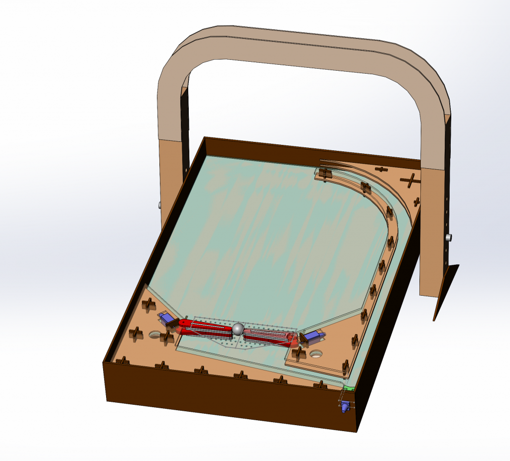
Mechanical
The 3d model is coming along nicely. The pinball box itself and the general geometry for most parts is done. Some minor parts and assemblies are pending redesign.
Marcus.
For now, there is not really any code that can be written for the micro controllers themselves. So, for now the Unity simulation is the only thing to work on.
Therefore, I continued working on the unity simulation, for this week. The spring that starts the ball was added, and a out of bounds detection system was also added. I also wrote some basic artificial intelligence that detects when the ball hits one of the flippers, and then triggers the flipper. For now, this is simply done by detecting when the ball collides with the flipper, wait 1 second. And then triggers the flipper. The out of bounds object is the large rectangle below the board. IT resets the ball to its default position. Wich is above the cube (pull spring) in the right tube.