Machine
At our meeting 08/09 the group decided to put down some parameter for our design. By drawing up the size for our gameboard we ended on an arm around 20cm. since our primary goal was to make an arm that could play “tic tac Toe” we wanted the parameter to be reflected in this.We also sat 4 joints in our design so that we could maneuver our arm more freely. This could also come in handy later if we wanted to expand on our hands function and use.
By doing a quick sketch in Solidworks the group got a overview of the arms mobility.
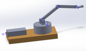 Figure 1: sketch from solidworks
After finding an example of an arm on the internet. We decided that it would be cool to hide the electrinical component. Referring to Fig 2 we see that the electronics in the back are hidden. Making the arm look more whole.
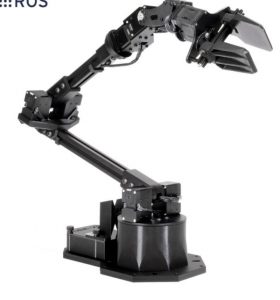 Figure 2: Kilde: https://www.trossenrobotics.com/widowx-250-robot-arm-6dof.aspx
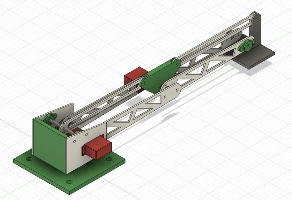
I also took some measurement from the servos we were planning to use so that when I started to design, I could place the servos directly into the design. I also took the names and number so that I could later find the specifics for the different servos and do some calculations for strength.
Problem!
We were planning on using a vacuum suction cup at the end of our arm, but the school did not have vacuum pump. therefore, will have to build one or go for another solution. Electromagnet was discussed. But we have to look a little bit closed on this. Buying a pump where not an option due to price of kr 2000,- for one pump.
Homework for next time machine will start on the design and primary on the board. This was so data could do test on the board. I will also start and try to come up with a more specific design that includes necessary strength, built in components, the primary goal for our arm and figure our how our joint could move the most smoothly.Electro
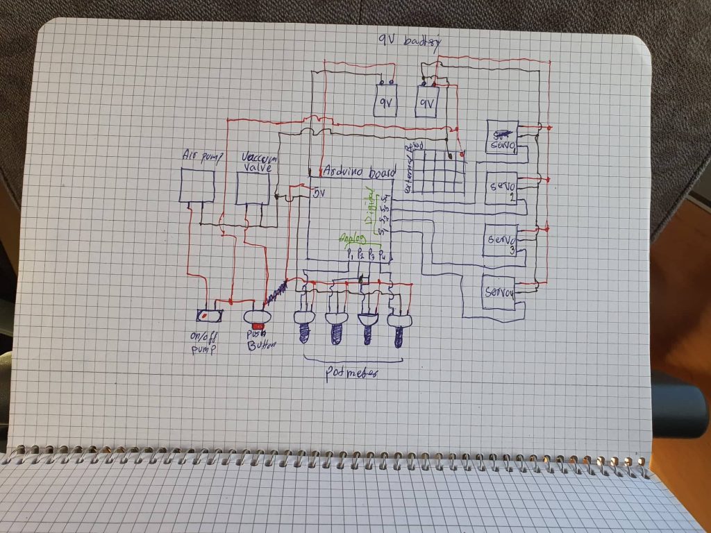
we have designed a circuit for the electronic part and calculated how big the battery should be and we end up with 2* 9V batteries, and for the servos we will be using 3 tower pro mg995 and one Towerpro SG90 9g mini servo.