Jens – final post from electro
If at first you don’t succeed..
After the demoralizing setback on Thursday, we decided to keep going. We felt that we were quite close to develop a working system and that we at least had to give it a real try. We only had three days until the final presentation, but it was better to fight for it and maybe fail again than just concede defeat.
We made two big decisions. The first one was to focus on using joysticks and HC-05 Bluetooth module for control purposes. The second was to use another motor shield (VMA03) on top of an Arduino Mega 2560. The change of motor shield had one big pro and two minor cons. The pro was that it can handle a tougher motor load than the VMA207, with 2.5A per channel vs 0.6A. This meant it would have no problem handling the somewhat high friction from the tracks and cog wheels. The first con was that it couldn’t handle more than two DC motors. It could pass PWM signal through to the servos, but i had to power them externally, which meant more wires in an already cramped space. The second was that because of the limited vertical space, i had to switch from UNO to MEGA to enable access to SCL/SDA pins for the QUAPASS LCD display as well as the Tx/Rx pins for the HC-05. I made the new wiring plan on the fly and coordinated pin number changes with Stian who was augmenting the code.
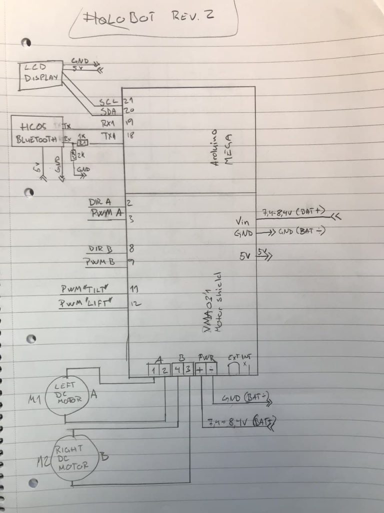
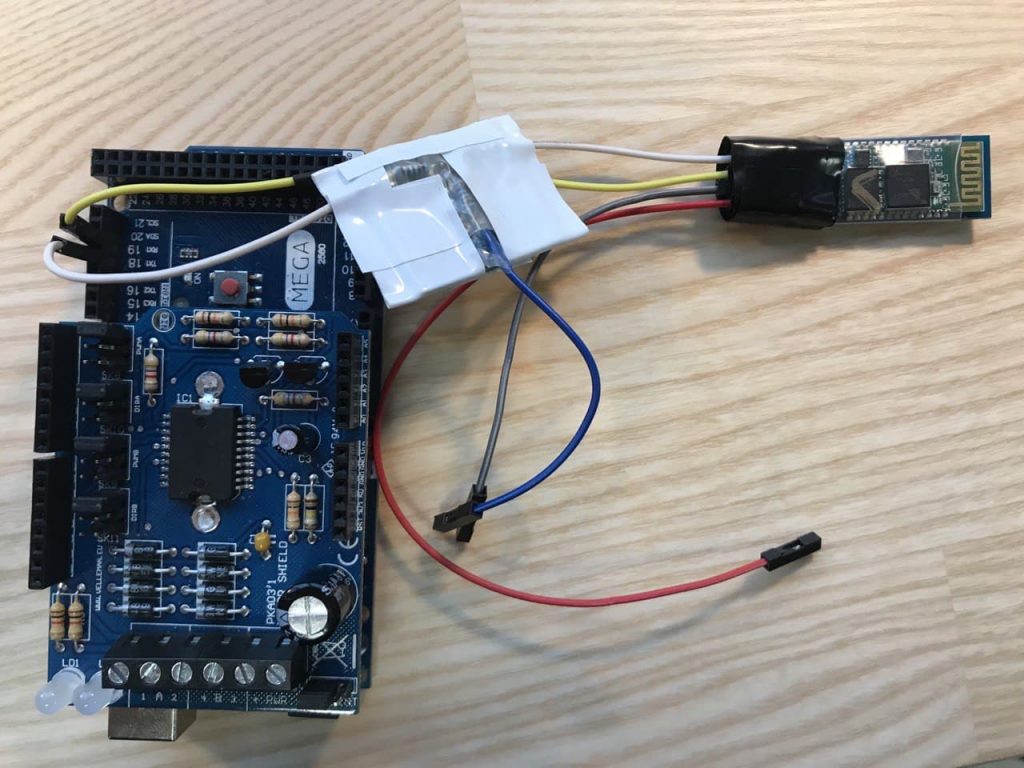
The Tx signal from a Mega has a 5V amplitude, while the HC-05 requires 3.3 on ist Rx (yes, Tx/Rx signals are crossed). I had to make a voltage divider small and durable enough to be placed in the robot, so i soldered 1k and 2k resistors on a piece of perfboard which i cut to size and then masked with adhesive tape.
I also trimmed the wiring and wanted to get rid of the big lumpy couplings, so i soldered header pins on a stripboard to make rails for 7.4-8.4V, 5V and GND. Put extra solder bridges between the pins as the copper strips were quite thin and the rails would have to deal with up to 3A countinous. The rails were glued to the hull between the microcontrollers and the batteries to allow easy access.
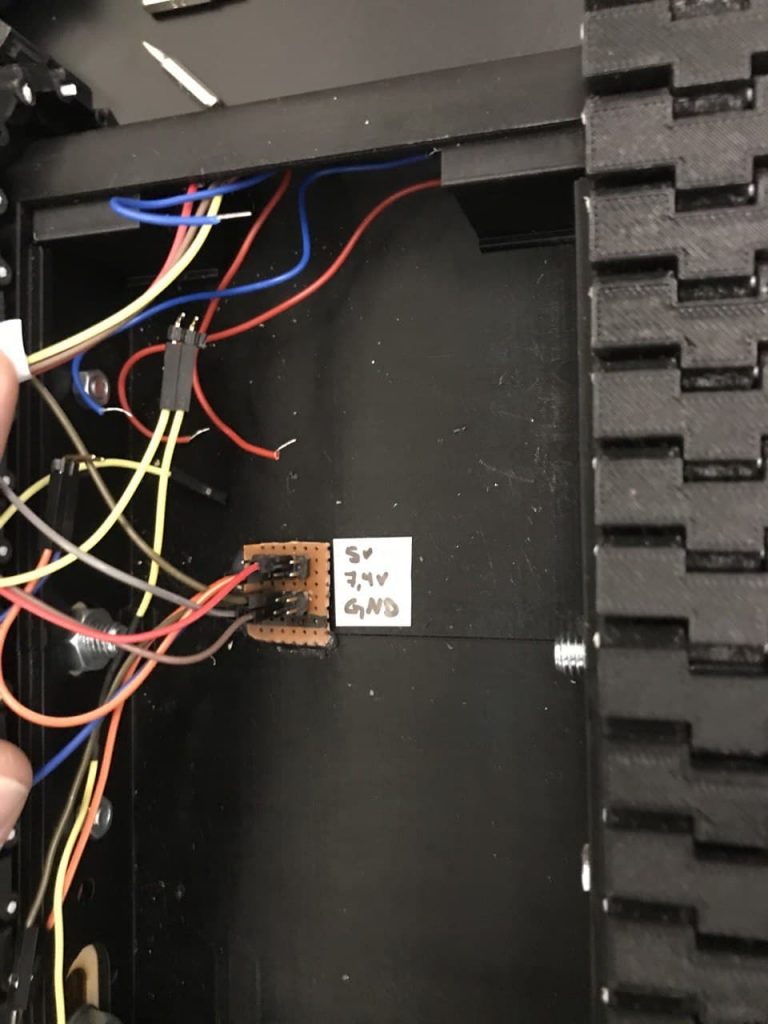
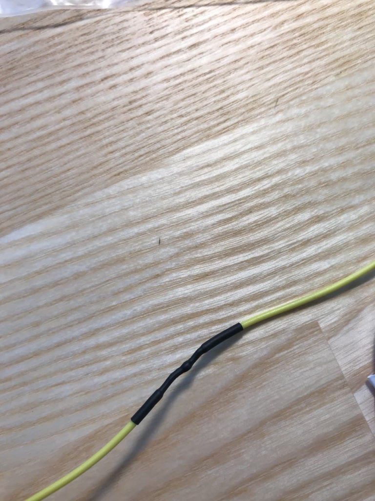
This little trick helped a lot more than i had initially thought, and i could now cut wires their exact required length as the couplings weren’t floating in mid-air anymore. Using mainly wires with heads, i had to cut out a bit of the middle, and join them again using a tiny but of solder and a shrink tube
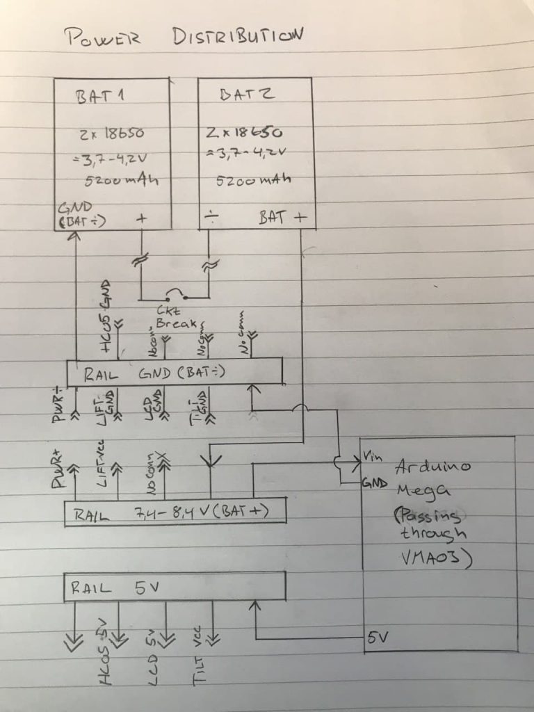
Power distribution now including rails
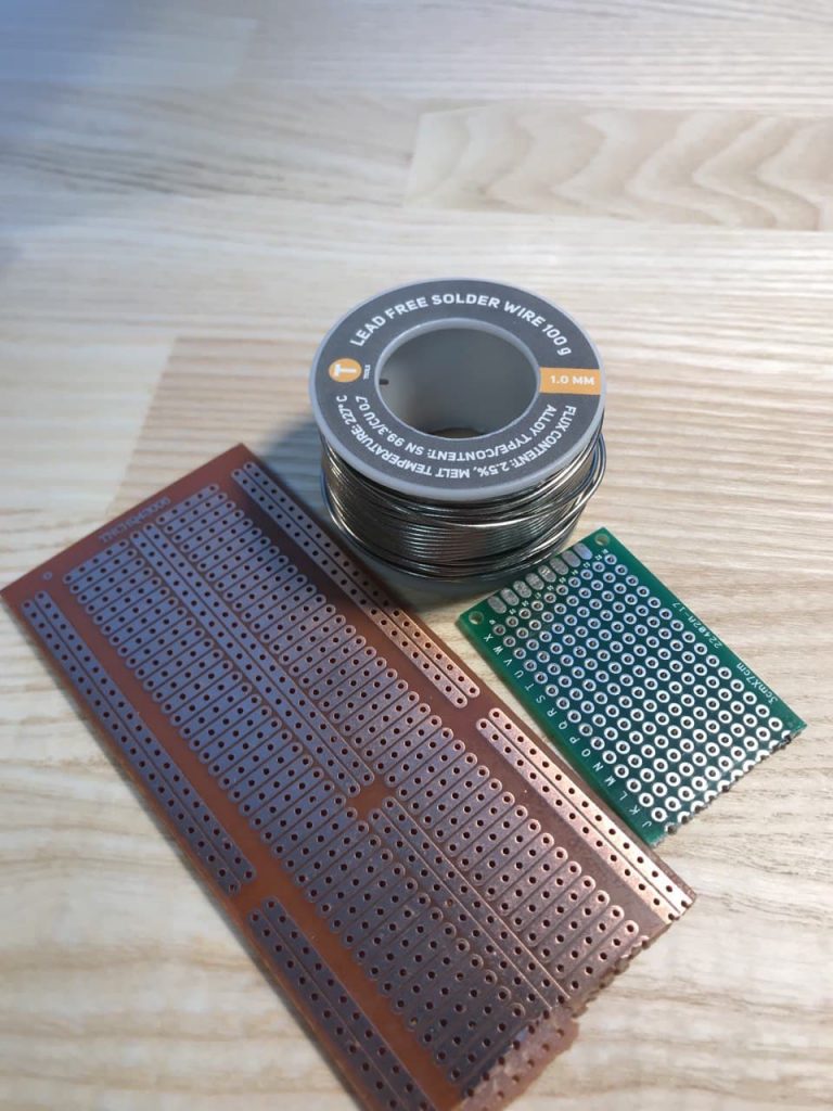
My new best friends ?