Mads
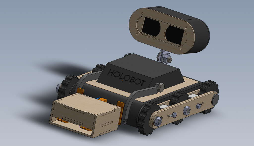
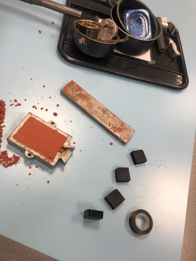
This is going to be a summary of the semester, the challenges, victories and quite a lot of failures. The idea of the Holobot was formed the second week into the semester. Group members had a big wish to use the HoloLens, but it needed to be incorporated into something mechanical. Thus the idea of controlling a modular robot with the HoloLens was born. The idea was to use the HoloLens to have extended control and to manipulate the vision of the user with the robot. So mechanically I was to make a robot, with an unknown area of operation. I decided to design and make tracks, as it was a new challenge I had yet to try. As shown in previous posts there has been a few different designs. I did want to make a track system with suspension, but in the end it was proven to less functional than straight tracks. The current system is still modular, so an upgrade with suspension could easily be mounted. Another big issue has been, space. The little robot has very little space as we wanted to keep it rather small. There is a lot of components that needs to be within the robot, so I had to be creative with the design to not make is a big box. The Holobot utilizes space quite well, which has helped with the assembly later on. The Holobot uses mostly 3D printing PLA, since I recently bought my own 3D printer. It also uses plywood, and it was intended to use cast aluminum. Though this was in the end redeemed unnecessary. Later on it did cast a piece used for weight in the Holobox.
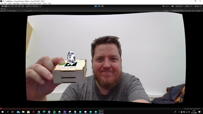
The Holobox is a box which is fitted with a QR-code. The idea is that when wearing the HoloLens, the user will see a different item on the box due to the code.
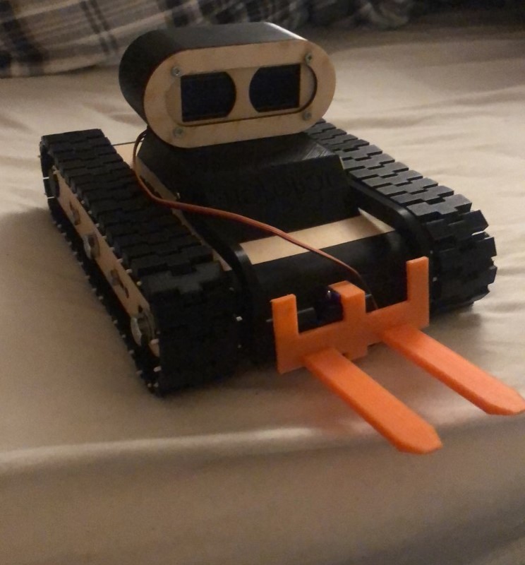
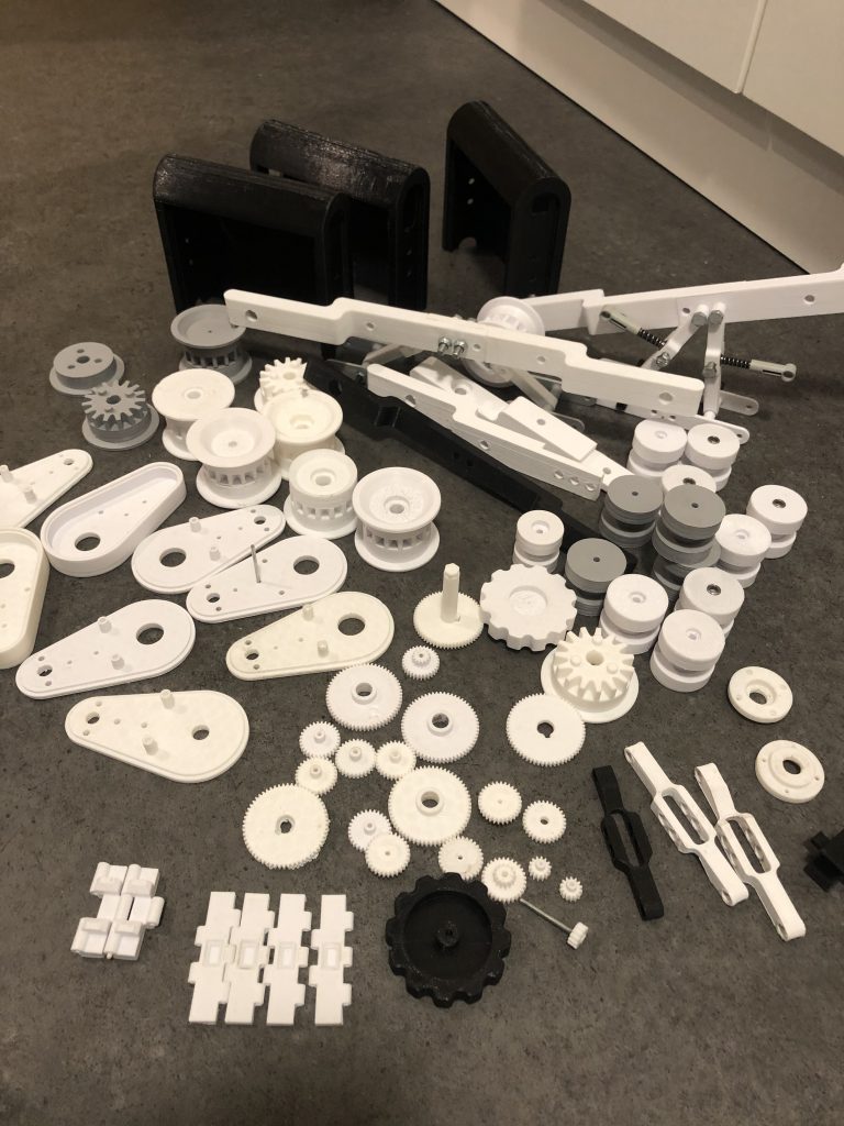
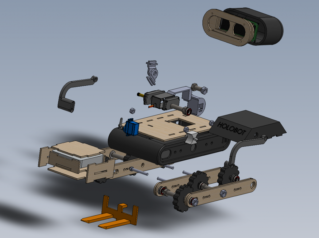
So to conclude. As seen in the pictures I have tried a lot of experiments this semester, and I have learned quite a bit. The final design as you can see in the exploded view ended up using a lot of bearings and spacers. This reduces friction and ensures the tracks run smooth, which we will demonstrate on Monday. I have tested the interface between mechanical components and ensured it all works properly, however the group has had struggles with assembling the electronics and testing it with the correct code. I hope to at least get to demonstrate the mechanical features.
Kjartans fantastiske blogg
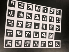
Aruco QR reader
An idea to be used on the HoloLens was QR reading on boxes and things around the room to distinguish the various items. By searching around, I quickly saw people had problems using standard QR reading, it was just too small and hard to read for something like the HoloLens that would be maybe a few meters away. A fix for that was Aruco library, I downloaded from a github I found and started testing it. I was able to make QR codes and add an object to a QR image. The problem was when I uploaded to test on the HoloLens the whole system lagged out and showed a developer error message, but it was not centred on the screen, so I was not able to read it. Because of time I moved on to another thing to add to the project itself.
Unity project files for this provided in readme file on our project github
BT Controller
Because of the limitations on IR, we wanted to add a Bluetooth controller to the Holobot, to more smoothy control its movements. First, we looked into adding a BT module to pair to a PlayStation 4 controller, but without the right profile it wouldn’t connect. The most common way to solve this was adding a USB-shield and use a USB BT-dongle. But as we had neither and no time to buy, we thought about the idea to just make a controller ourselves, we found 2 BT modules for Arduino and 2 joysticks and started to connect it all.
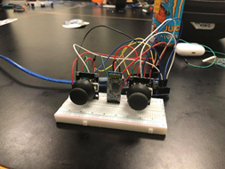
We were able to program the BT modules to be master and slave and connect them. but somewhere when sending the joystick movement information, it would fail. We got one Arduino to send code to the other to turn on and off its LED light, but anything more than that would not work for us in time. Arduino code for this on the github provided for our project.
Stian, Holobot conclusion
We made a finalized code to work with the HoloBot, that takes IR signals from a receiver and preforms 6 commands. Forward, Backward, Right, Left, Lift up and Lift down these worked with 2, 8, 6, 4, Vol + and Vol -. The directional buttons used the motor library to move the motor for x number of seconds before releasing them again. Turning left and right was done by giving the motors different directions to go. Lift up and lift down was done with servos and we used a library that gives a variable speed so the object it is lifting does not go flying. We got the IR to work with the servos, but the motors did not work with it. We figured out to late what it was which is that the IR library uses the same clocks as the motor library this makes them not compatible. We did manage to fix it in the end, but it was to late for us to get the robot running at that point. Everything that we tried is in the github repository https://github.com/StianFHatlestad/HolobotBackToBasic .
The HoloBot have eyes with a LCD display, we connected the LCD with a I2c connection and used wire and liquidCrystal_I2C libraries. We made our eyes with the custom chars witch the library supports up to 8. We then made custom eyes for the robot instead of using normal symbols for the job. Finally we added some life to the robot by making it blink it’s eyes using the millis function.
Jens
Putting everything together
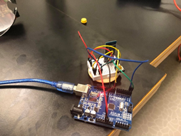
After having checked the wiring plan for motors, charging, battery series switch (which functions as the on/off switch for the whole thing at the same time as the series connection has to be broken in order to charge the two battery packs) and verified that voltage and current ratings were within limits, i met the rest of the group at the university. We first tested the DC motors and servos using the UNO and the shield, and they worked fine. Then we started to put everything together. We knew it would be a tight fit. I had supplied ample length for most of the wires that were soldered on to the various components, so that they could be cut down to a more suitable length after placing battery packs and UNO+shield where it seemed most practical. We had to solder headers on top of the shield to access various logic pins. Checked for continuities and there were none other that those intended. After much trial and error where we could not get the LCD display or IR sensor to work, we found out that the 5V output from the shield only read 1.2V. This is way less than their minimum voltage requirements. I checked my wiring for faults and possible shorts, but couldn’t find anything. I continuity-checked the shield for possible shorts, but found nothing. I checked if there was any unwanted connections between the shield’s bottom side and the UNO, but no. The fault might lie in the board itself or in the Motor Driver ICs that are mounted on it. I might add that when i came home that night i also checked the UNO with 7.5V on the Vin pin (Vin was at about 8.3V when we tested at the university), and the 5V supply pin from the UNO read exactly 5 volts no matter what GND pin i used as reference.The next day i plugged in the UNO again, ran a test code for motors and they functioned perfectly. The 5V pin also read 5.04 volts, so i have no clue what happened the day before.Checked over all voltages and connections and didn’t find anything faulty. Tested servos response to input from the IR, and got them to work with a test script, but not with the full code. We spent many hours debugging and testing, but could not get it to run. Wiring and coding schematics as follows:
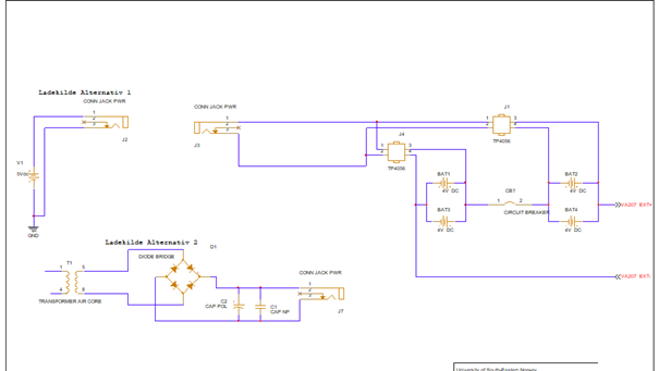
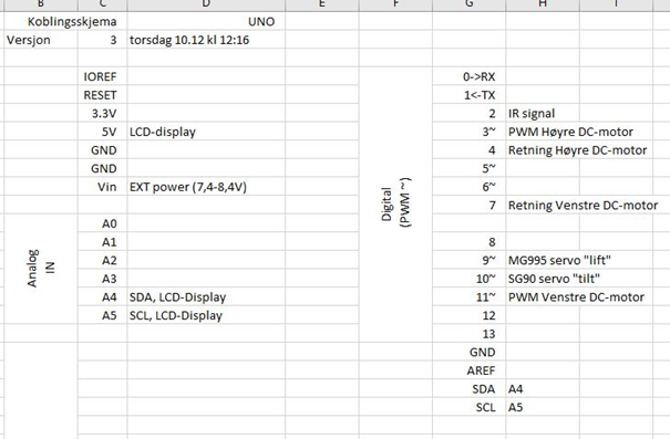
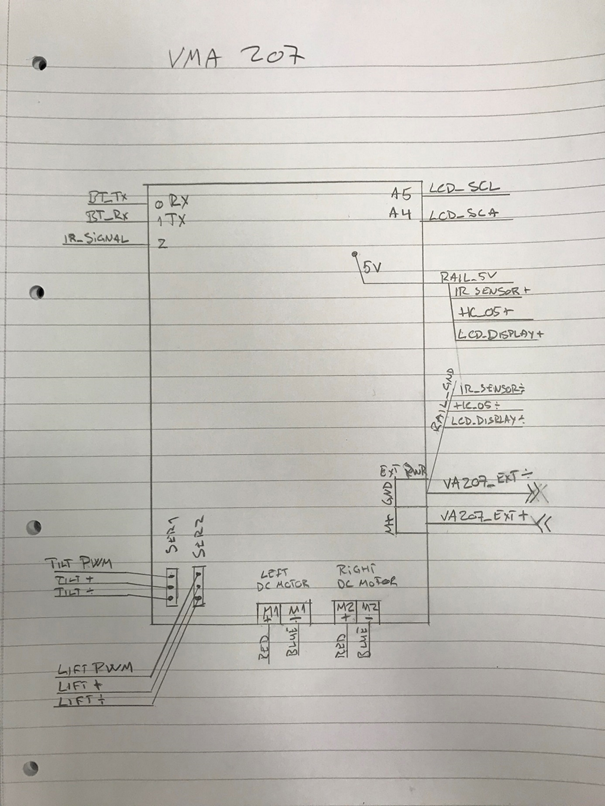
About the charging circuit: I used double 18650 batteries in series to drive the motor shield with 7.4-8.4V external power, but only had LiPo charging chips for 3.7-4.2V. The circuit break is used in order to charge the batteries. About the 5V and GND rails: As we tried different forms of communication, we needed more connections to 5V and GND. About the Excel list of pins: This is for the computer guys to use when coding for the Arduino UNO.
In retrospect
When I was researching induction charging, i should have tried a solution earlier than i did. The coils I made probably had too few windings, and i wasn’t able to measure their impedance (i don’t have an adjustable pulse generator at home, and the multimeter i borrowed did not work). About the rest of the circuitry: I am quite content with having gone for using a motor shield, as breadboarding would have been too spacious. I suspect my shield was faulty, though, because the motor driver ICs seemed to generate some heat even when the motors weren’t connected or being operated. I managed to supply sufficient power in volts and aH to the whole robot. Might have tried to fit everything a couple of weeks earlier than I did, but I had to use time on other things.