Adapting to an issue (Mads)
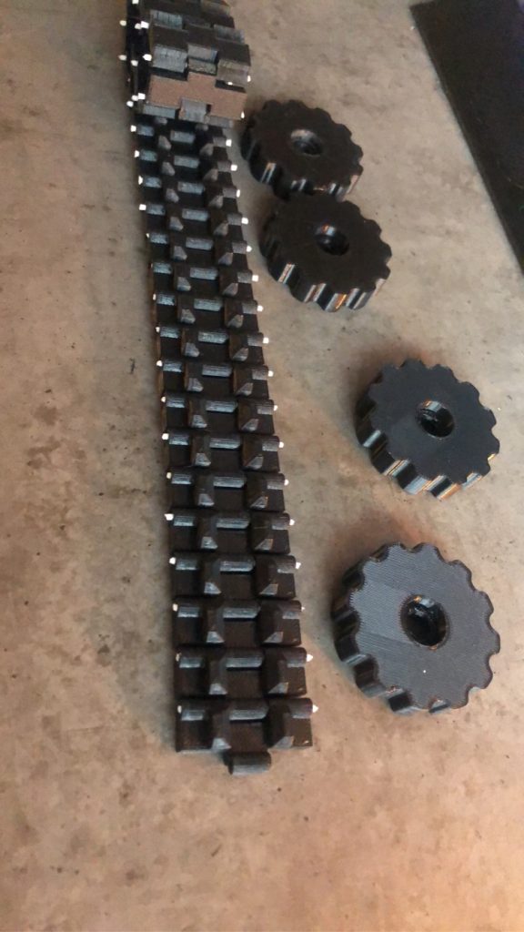
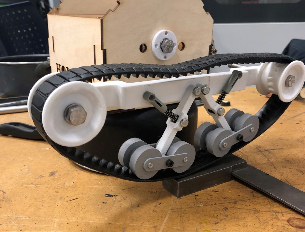
The last weeks I have been more concerned with developing the mechanical aspects of the Holobot rather than writing. Countless hours has been spent designing, printing/cutting, assembling and testing with mixed results. I wanted to create a module based track(beltemodul) which could easily be installed on different vehicles and robots. This would need to be robust, and have suspension so it could operate in different terrain. Perfect for a project like this where the area of operation is unknown or to be determined.
This was sort of a success, but more on that later. First the gearbox.
The axle for the drive wheel was quite far away from the body of the robot. We wanted to keep the robot relatively small, as it makes it easier to produce parts from 3Dprinting and laser cutting. Decent tracks is difficult to find cheap, and these ones are quite superb. But they did not come with the proper measurements, which meant the scale was slightly off. So in order to keep the two DC motors close to where we wanted the center of gravity I decided to experiment with making a 3D printed gearbox.
The gearbox problem
The gearbox would allow us to keep the DC motors close to the body of the robot, but would also give us more torque. We have 2x of RK-370SD-4045 brushed DC motor 12V.
Torque: 26.3gcm
speed: 4310rpm
We found these motors cheap after the belt-module had been made, and in hindsight I should have done much more research. I had very little to compare these numbers to, due to my experience with small DC motors is mostly just trying and experimenting.
So I did some research and learned it was very possible to design and 3D print a fully working gearbox, and I could easily manipulate the RPM using the gear ratio. This video series was great for explaining and simplifying.
So I designed our gearbox using the toolbox utility in Solidworks. The DC motor has a permanent fixed 10 tooth spur gear fixed to it’s axle, so using this as a base I geared it down to a ratio of 6/1. I fixed the gears to axles which again sit in a bracket. The distances is driven by the gear radius which again is driven by the number of teeth, module and pressure angle. Printing the bracket at high quality worked great and kept the distances intact.
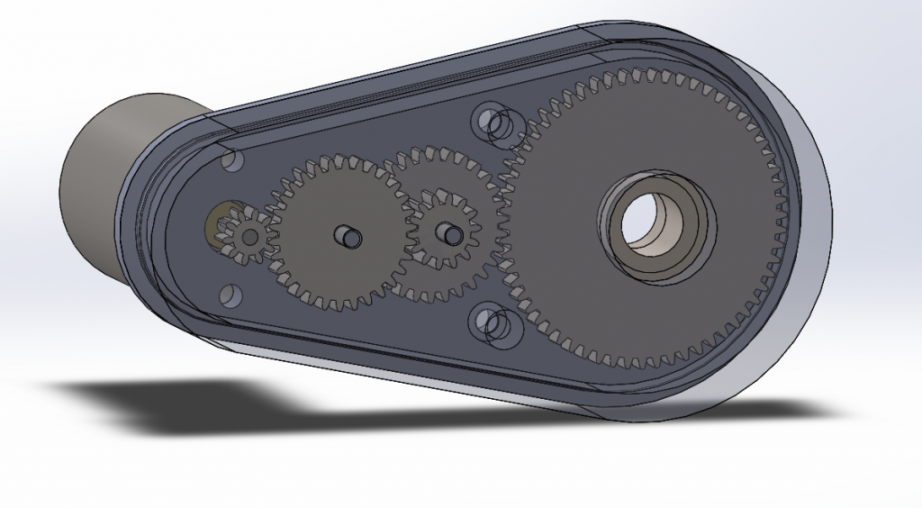
Gearbox test,
The gear that is not rotating is simply used to keep the gear below from flying up, since the bracket cover is not attached.
So, then both the tracks were in place, gearbox was made and the body of the robot has been laser cut and assembled. And it was time for testing. To my disappointment it did not budge. There was simply to much resistance and friction in the system. So I concluded that if we reduced the friction it would be easier for the motor to start. So after redesigning it with bearings now to make the tracks run smoother I tested it again, but the same issue. The motor does simply not have enough torque to pull the tracks around. The amount of gears also contribute to loss, as well as the long axle attached to a rather large drive wheel. All in all this requires a much larger DC motor which is geared with preferable metal gears, attached directly into the axle or the drive wheel.
The solution
After doing more research on geared DC motors we have found a decent alternative that is student wallet friendly. N20 DC12V 100RPM Gear Motor Miniature is a brushed DC motor with 100 RPM, and stall torque at 6kg/cm which is a huge improvement from the previous motor. It is smaller in size which fits well with the plan ahead.
Putting the current track system aside I will design a much smaller and simpler module fit for indoors. This will be much more reliable and will give my group something physical to run test with. In the beginning of this semester I experimented with fully 3D printed tracks, and continuing with this I will be making this new module. If I can get the bigger old module with suspensions to work as well, I aim to make them changeable so you can change track system depending on the area of operation.