Project Status
This week we had a meeting to agree on the design moving forward. We agreed on the final specs, which includes to limit the movement of the machine to one axis. It also became apparent that a 50% scale model would be more practical and it would still be able to show our proof of concept. We feel like we are currently in a good position and have the most essential pieces in place for our project as well as the components needed.
Halvard
This week we the mechanical engineers have started to gather the supplies that we will need to start constructing the machine. I have bought some more filament for the 3d printer to prepare for the manufacturing process. This week I have started to manufacture our final iteration of the hockey machine. I started by 3d-printing the parts for the main assembly, it will consist of 20X20mm square steel tubes. These tubes will be connected with 3d-printed parts to ensure easy maintenance and to make sure that we can make changes to the design if needed.
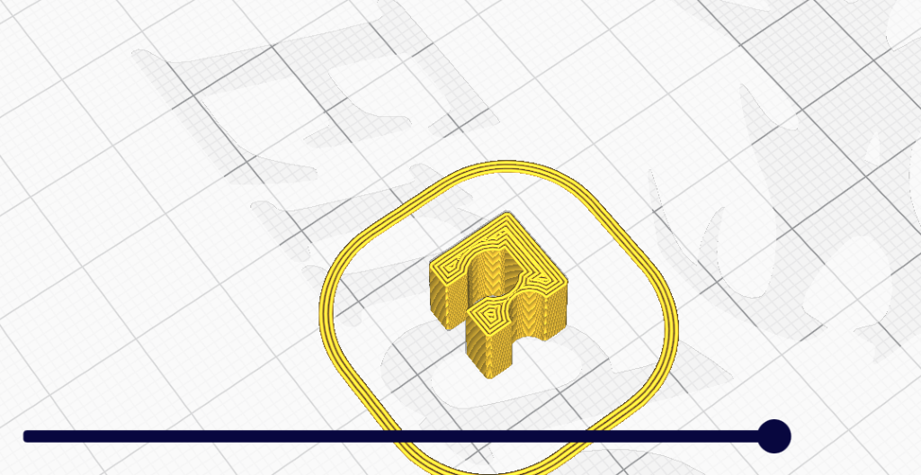
For those parts I have choose to use PETG since this will give us sufficient strength as well as it not being too brittle. The PETG was first placed in an oven at 60°C for 2 hours to make sure that it did not contain any water. This was done since PETG is hydroscopic, which means that it will absorb moisture from the air if exposed to it. We think we are able to get most of the building on the machine done by next week.
Anders
The past week I started to implement a binary logical check system to ensure that the windows application is always keeping up with the Arduino. This is done by analyzing all the serial communication coming from the Arduino and then running it through an algorithm that shows the right content in the UI.
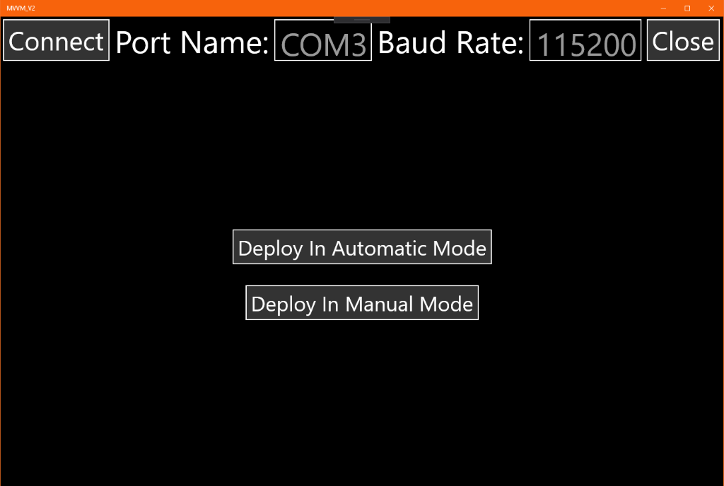
Other than that, I have also redesigned the UI to further simplify the number of options you have at any given moment to reduce the chance that the Arduino receives unintended values from the GUI application.
The new design splits content into three panels, one to change between automatic and manual control of the Arduino:
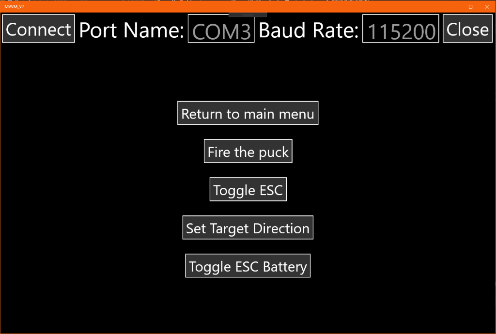
One to select what between the different manual functions in the Arduino code:
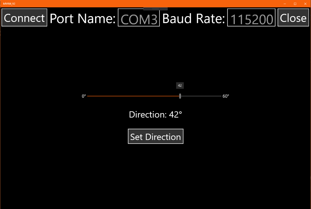
And the final one which enables the user to set the target direction value:
Other then that we have the connection panel at the top, which is visible at all times, and that I plan to have showing the connection status of the serial connection in the future.

Gaute
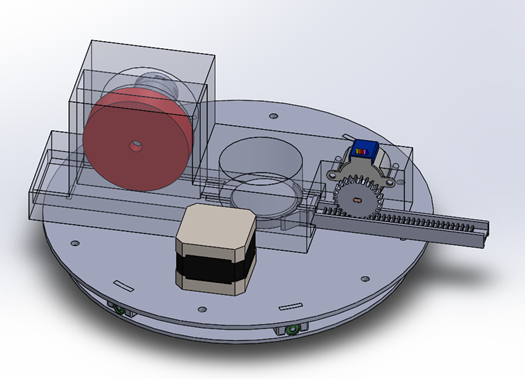
The focus this week was on making the feeding mechanism. As per now it the choice stands between using the servo, I made last week, or using a stepper like shown under.
Nicholas
Software
I started this week with updating the existing Python programs to be more user friendly and to more easily move between running tests on my own laptop and the Jetson Nano. The first step here was to detect what platform the program was running on. Then I would need to have different methods based on what system it was running on as handling of USB ports are done differently between Windows and Linux. I also made other small improvements to the program so that more of the process can be automated. There are now several flags defined at the start of the program that will make selection of different modes easier when testing.
With the new stepper I had to rewrite the Arduino code in order to work with the stepper driver. The new stepper driver only requires two inputs. On which states the direction of the stepper and the other registers pulses and moves the stepper accordingly. How far the stepper will move on one pulse is determined by the DIP switches mounted on the stepper driver. The setStepper() function now looks like this:
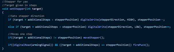
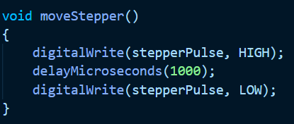
The function now sets the stepper direction depending on where the target is located. Then the stepper moves one step. The moveStepper() function is super simple and only sends a pulse to the stepper driver:
Electrical
I also made some progress on the electrical system this week. We changed our stepper to a NEMA 17 that I borrowed from an friend. However, the drivers he had used for this were rather cheap and simple. I decided to replace these ones with one borrowed from Steven. The new one is based on the TB6600HG, or more correctly the TB67S109AFTG. This driver has much better heat dissipation and allows up to 1/32 microstepping.
After reading the documentation for the module I wired it up and wrote a small test program for the Arduino.
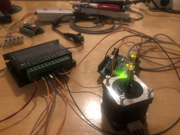
Another great thing about this new stepper driver is that it supports input voltages in a wide range. This gives us greater flexibility in what battery to use for our project without needing extra components to step the voltage up or down.
With the us having decided what components to use I could start working on finishing the different drawings and schematics for the projects. I also wrote a BOM and sent to Halvard and Gaute so they could start to design a compartment/mounting for the different components.
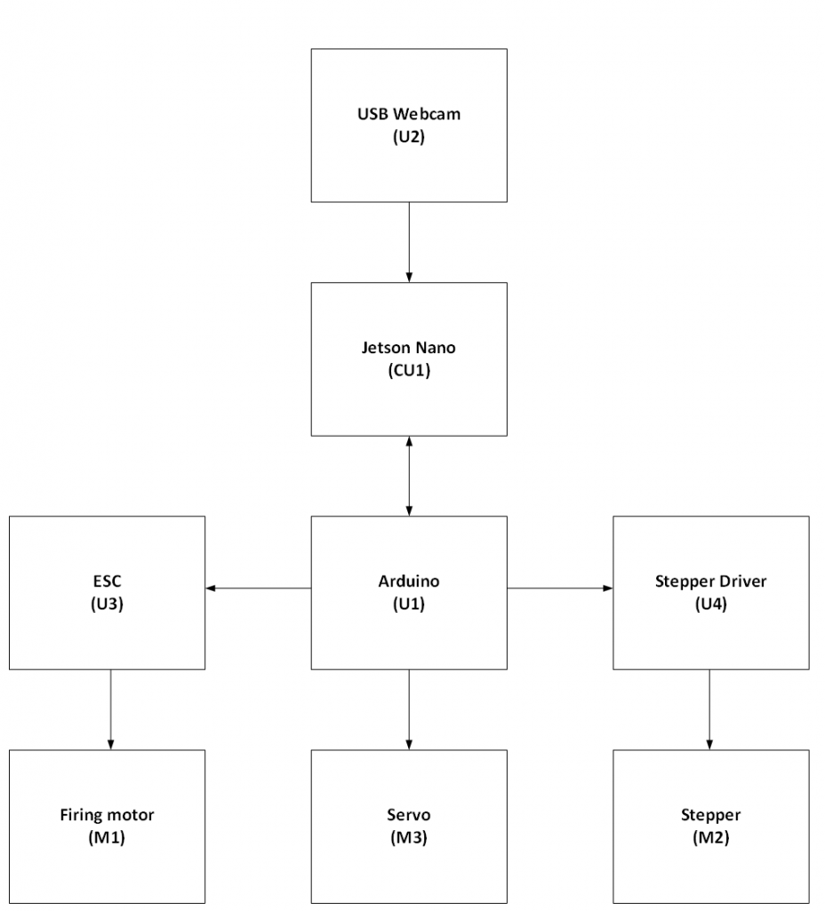
I started off by drawing a block diagram that shows the different connections between the different components. I also assigned each major component with a ID which will be referenced I other drawings as well.
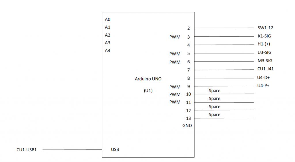
Based on this I updated the Arduino wiring diagram whit specific connections.
Next sprint I plan on finishing the other drawings which includes a wiring diagram and a layout drawing.