02.10.20-09.10.20
During our meeting this week we revisited the requirements we had set in week 2, they know look like this
A:
- The system should shuffle cards
- The system should hand out cards to each player
- The system should identify cards via image recognition
- The system should make calculated decisions based on dealt cards
- Can move the arm (180 X axis and 180 Y axis).
B: The quality of the application would be greatly improved by this requirement
- The system should be controllable by the players wirelessly
- The system should communicate and interact with the players
- Can reload the card decks.
- Can keep the cards in the hand against gravity.
- Can move the arm fully (360 X axis and 180 Y axis)
- Can perform certain arm movements. (Wave, etc.)
C: This feature would be nice to have; it may consist of cosmetic changes, non-critical inquiries, or other
- The system should collect cards from players autonomously (No longer applicable)
- The system should hand out cards in front of the players
- The system should know multiple card games
- The system should be able to smartly bet money
- Can reload the card decks automatically.
- Can make sounds and noises in correlation to game.
Maskin (Simen):
After getting a reality check from finding information about the servos, the servos will probably have difficulties turning the heaviest part of the arm (Near the base). May need to double the amount of servos, complicating the arm and coding substantially. Or find some genius way of reducing the weight of the arm/payload.
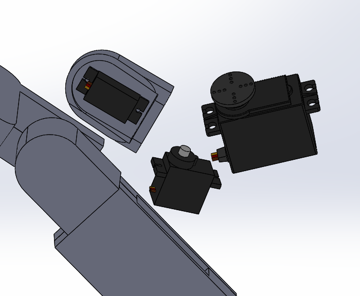
Continuing my design adjustments to fit the parts for using servos, I will need a specific size of the servo to have the parts best suited for realistic use and printing.

The hand now has a rail to connect the cartridge in, to easier keep the cartridge in the muzzle. The cards will still require some blockage to keep them from falling out at once when picking them up. Perhaps we could get two birds with one stone by using the servo meant for handing out the cards to apply enough pressure to avoid slippage.
Elektro (Sondre):
This week Danial and I had a discussion with the electro teacher in regards to a PWM driver. We were curious about a good solution to running the motors, sensors and such, and myself specifically was curious if buying a dedicated PWM driver for the Raspberry Pi was too small of a task. One of my first ideas was to use a FPGA for the job, but as I’ve talked about earlier it was a bit overkill for this task. Therefore, the teacher gave us the idea to use an Arduino by utilizing a Serial Peripheral Interface (SPI). We have had the idea of using an Arduino earlier, but I was afraid that it would be too easy of a task. I might have been to short sighted while I first thought about this, because using a SPI communication between the Raspberry Pi and Arduino seems like an effective way to run the components of the system, and allows us to carefully determine how much data we need to transfer between the computer and microcontroller, and the Arduino also saves the Raspberry Pi some processing power by doing a lot of the computation it self.
While I remember that we briefly learned about SPI in a course we had during our first semester, I have never utilized it before, and in no way communication between multiple microcontrollers and such.
With that said, it does seem that SPI is a rather simple and effective way of communication and data transfer. SPI is an interface bus which sends data between devices, and such devices communicate in both directions using a master-slave architecture. It is a synchronous data bus with the master device providing a clock speed that the slave devices receive to keep it in perfect sync. In the figure down below, we see that SPI utilizes 4 wires. SCLK is the clock, MOSI stands for Master Output, Slave Input, MISO is Master Input, Slave Output, and lastly the SS stands for Slave Select.

This means that the SPI bus allows the master device to be connected to multiple slave devices, and uses the SS connection to select which slave the data is transferred to. In our case however, we will only be using one slave, which is the Arduino, and the Raspberry Pi serves as the master then of course.
As I mentioned earlier, using a SPI to send protocols to the Arduino allows us to save some of the Raspberry PI’s processing power, and we’ll need to know how much of the work the Arduino can do.
When using this system, it’s important to remember that the Raspberry Pi is a 3,3 volt system while the Arduino is a 5 volt system, so I’ll have to keep in mind to regulate the voltage difference. Furthermore, there might also be a need to check if our setup requires some work to make sure that it is electromagnetic compatible with other parts of the system and what not.
Since Danial is the one that will be programming the motors and such, I’ll have a discussion with him about how we can incorporate SPI to our system and if he thinks it’s doable as well. I do look forward to working with this type of interface, as it’s the first time doing anything similar and it seems like it provides some valuable experience since SPI is an industry standard in terms of embedded systems.
References: https://en.wikipedia.org/wiki/Serial_Peripheral_Interface
Data(Danial):
I have shown that I have worked further with the development of ROS and how our system should be put together. We will use 6 servo motors to move the robot as we wish. I started by implementing a node first, to keep it simple. If the development goes the way I want then I will implement each of the 6 motors to 6 nodes. So far I have made a test node, and got this to start with a master node. This has been a successful test, I will now start with the development of the servo motors and their movements. This will be exciting!
Data(Azim):
This week was a busy one for me. I had several assignments in other subjects that were due within the week that I had to prioritize. So, the meaningful work i did this week was simply continuing working on the scripts from last week, specifically the image processing algorithm. I also coordinated with Bjørnar for the object detection, since I don’t have the required hardware to run it on my PC, I uploaded the labeled data and the scripts so Bjørnar will run the custom model on his PC.
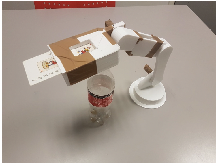
I also had discussions with our group members regarding exactly where the camera module would be placed in order to specify how much of the camera angle would be on the playing cards, whether we would have a dark or light background and other parts surrounding the camera angle and playing cards in order to know figure out every aspect of the design so I can modify the image processing script to make it as efficient as possible. Right now, the idea is to place camera module pointing above the card that is showing, as you can see from the picture. This will be sufficient since the camera only has to pickup the suit and the rank of the playing card.
Data(Bjørnar):
Similarly to last week I coordinated with Azim regarding the object detection. He had set up image labeling and other parts of training our model, but the actual training of the model would be done on my PC.
I started training the model and it seemed to work as it should but there was practically no progress, i realized this was because it was running using my CPU and not my dedicated GPU. When trying to train the model using the GPU I got error upon error that I solved one by one, most of them could be fixed simply by changing some paths and files in the directory. When I met an error that I could not solve I decided that restarting the process was the smartest thing to do, even though this is always a very hard choice to make. It was after downloading and setting up tensorflow the second time that I managed to get the training model running. Now it was just a matter of optimizing the hardware resources it could use for it to work fast without crashing.
Here is a list of what models and methods we used to train our image recognition model:
Framework: Tensorflow 2, we used the Tensorflow 2 framework as Tensorflow is the most widely used and supported framework for these kind of projects, the second version of tensorflow is now stable and more efficient so we opted for this.
Model: my_ssd_mobilenet_v2_fpnlite, we used this model as it is one of the easier models to run. This is crucial to us as we will run it on a Raspberry with limited hardware resources. If we run into problems with accuracy or framerate we might change this later.
Hardware for training: Nvidia GPU (RTX 2060), we trained the model on my desktop pc with a powerful GPU as this is immensely faster than training on the Raspberry or even a powerful desktop CPU. We wanted to set the training up on a fast computer as we may run the training dozens of times with different images and settings.
Images and labeling: So far we have trained the model by labeling the entire cards in images with various backgrounds. We might change and train the model to just look for the jack and value of the card instead of finding the entire card. We think that in the final product the camera will only see a corner of the card, so we will most likely train a model using only corners of cards.