Anders
This week there has been no work on this project from my side, due to my hospitalization as mentioned in the previous blog post. Anyhow, stay tuned as the others most certainly have something to show off!
Halvard
I have mostly worked on producing parts and testing them so that we will have some numbers for our budget of forces acting on the system. Gaute and I started testing the materials we are going to use this week. I have also started modelling the subsystem for the magazine, firing mechanism and the plates for mounting the electronics.
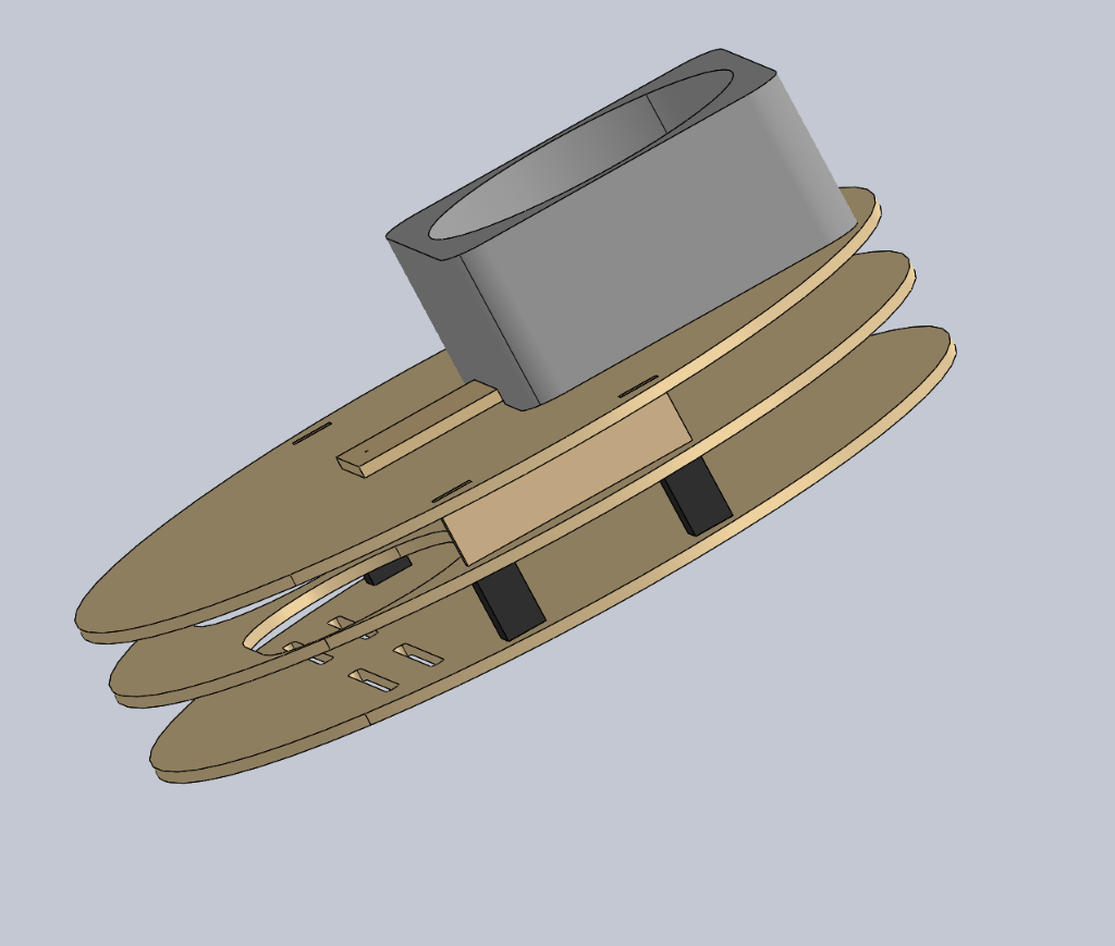
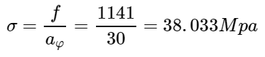
This is our proposed firing mechanism and the magazine assembly, the hockey-pucks will be stacked in a tube (PVC, etc.) and then they will be pushed into the spinning wheels with a servo. Most of the parts in this sub-assembly are intended to be produced with a laser cutter that’s why they have a rather simple look.
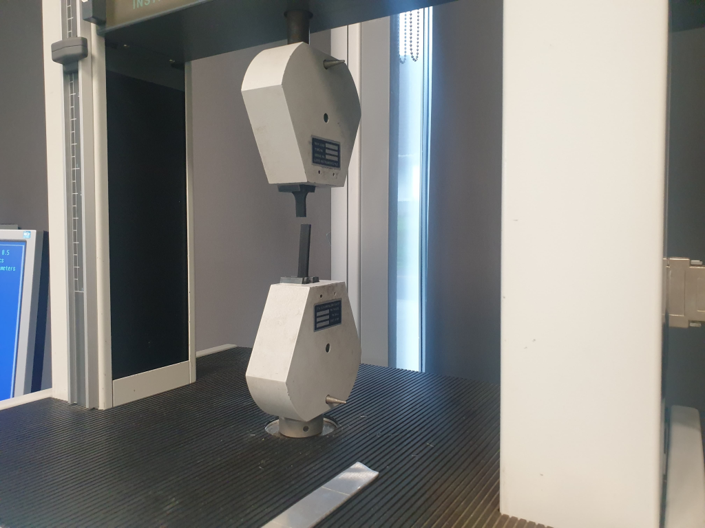
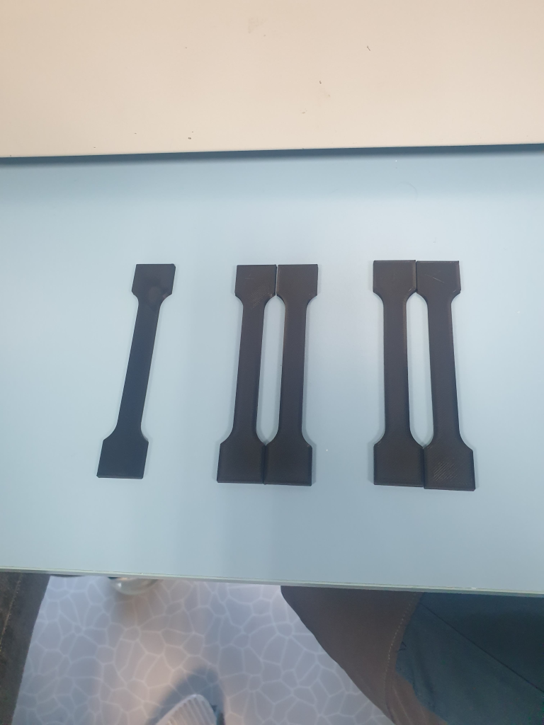
The first series of material tests (ABS, PLA, PET-G, Nylon, etc.)
This is where most of my time has went this week. The test parameters are as following; each material is being tested 5 times and the value will be the average, in some cases I will also list the spread. As well as finding the anisotropic properties of the 3D printed parts.
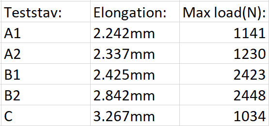
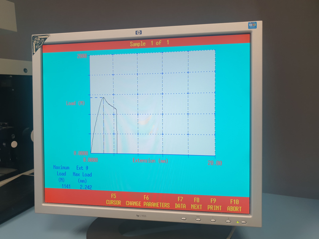
Her is the formula for the tensile strength for the regular PLA horizontally printed at 210 C @ 25 C:
This is right in the expected range, for the one printed vertically we had a σ = 18.342Mpa. This is what is known as anisotropy. This shows us that we also must take the orientation of the print into consideration during the design-process
This research will lead to a more thorough publication next week when we have tested all the materials and treatments for the materials.
Gaute
This week I worked on several things. I made some adjustments to the web-cam module that I started on last week. So now the load from the web-cam isn’t directly on the step-motor shaft, but rather on an axial bearing, this will reduce the wear and tear on the step-motor to a minimum.
I also made some mounting guides for the frame. They will make the assembly of the frame easier for us since we won’t have to weld anything. Makes it faster to build, and easier to perform any maintenance and disassemble.
But what took up most of the work hours this week was to adjust and fit the launch-mechanism-assembly to the frame. I took quite some time since the measurements wasn’t in the same scale as the frame-assembly.
Nicholas
Electrical
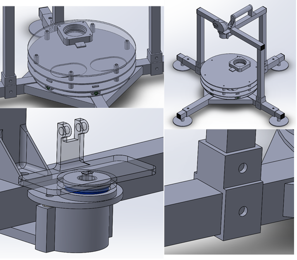
I finally sat down an learnt how to make components in Eagle and was therefore able to create the schematic draft for the project.
Software
So this week I spent most of my time researching and reading up on TensorFlow and machine learning. Therefor I don’t have too much to show for this week. I spent a lot of time reading and writing example code seeing the effects of overfitting the model and how changing the number of layers and the layers data affected the model. Our goal is to use our own trained model for the object detection to improve the performance as it would only have to identify 1 class instead of 80 as YoloV3 does.
One thing I could mention is that since I have a Nvidia GPU installed in my computer I could leverage CUDA to run model learning on the GPU instead of on the CPU. After many unsuccessful attempts at installing the necessary drivers for CUDA I found out that I had to uncheck the “Install Visual Studio Integration” part. More information about CUDA can be found here: https://developer.nvidia.com/cuda-zone
The goal for next week is to get some work done on the custom machine learning model and see how that goes. I will also probably start to look into running the model on a Raspberry Pi with TensorFlow Lite.