This blog is delayed by over a week due to unfortunate circumstances. Anders, our blog responsible suddenly went ill last week and was admitted to the hospital. Everyone from the group whishes you a speedy recovery Anders!
Gaute
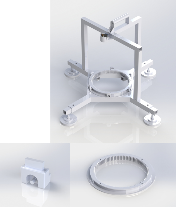
Hopefully this week I made the last draft of the glidering and the positioning blocks to the prototype. Ended up making some slots to the positioning blocks to place some bearings to reduce friction between the blocks and glidering. Made the topframe to which the camera is supposed to be mounted, and also a carrying handle. Might eventually fit som plexiglass walls to the topframe for protection.
Downloaded the step motor from grabcad;
https://grabcad.com/library/rohs-step-motor-28byj-48-1
Halvard
This week I have been focusing on making parts and setting up for material testing as well as looking at the intended operating environment of our system.
Material testing
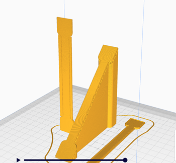
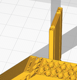
I have started to print some of the test rods that I have modelled and sliced. In this test it is important to look at the way the layers are built up. If they are printed horizontal, vertical or in an angle. This is important because almost all plastic (FDM) printed parts will have anisotropic properties. This means that it has physical properties which has different values when measured in different directions. This is done to make sure that we have a budget for the forces that will be produced and to know where we can use the differently produced parts.
Considerations of the environment our system will operate in
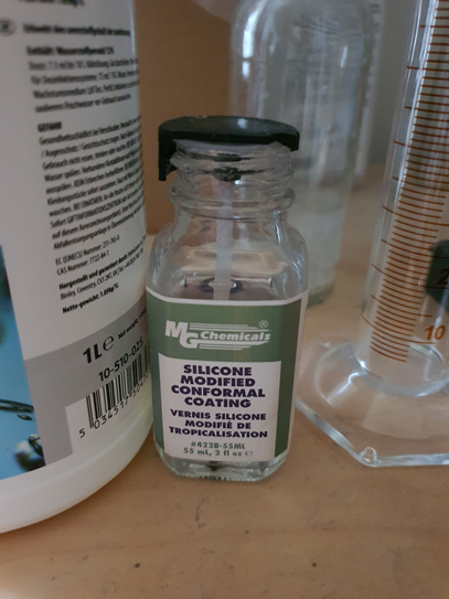
Our system will operate in an ice hall which means that it will be exposed to water in the form of ice. We also must take into consideration that the machine will be brought in and out of the ice hall. This means that it will develop dew all over the machine. As a way to manage this we will have to use a coating on the electronics, we propose to use silicon conformal coating since this will give us protection from the environments as well as some protection from the vibrations during use.
Nicholas
Software
I haven’t had too much time this week to focus on the project, so I only made small additions to the software.
First off, I added the ability to send multiple values to the Arduino in a single message where each parameter is separated by a ‘,’ and each message is ended with ‘;’.
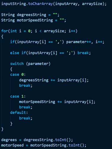
The code shown in the picture above converts an incoming string to an byte array that is then converted to strings and then to int’s. The nice thing here is that the switch statement can easily be expanded to accommodate more parameters sent across the serial line. The downside to this solution is that it requires the sender to send in the correct format/order or else problems will arise. Also, currently the code is embedded straight into the main loop for automatic mode. It should be however be turned into it’s own dedicated function so that it could more easily be reused other places in the program if necessary. Most notably in the manual mode part of the program. I also fixed a minor issue where the firing mechanism wouldn’t work as it did not take into account the extra steps that are added due to int –> float loss.
What’s next
There is still work to be done on the Arduino code, especially regarding the stepper and the extra steps. I think we have to redo it so the additional steps are only counted based on the delta of the current position and the new target position rather than being based on the stepper having reached the previous position.
I have also started to look into TensorFlow so that we might be able to write the image tracking part and make it run on a Raspberry Pi with acceptable performance. Right now we are using YoloV3 running on my laptop, which is fine, but we want the machine to be portable so we need to able to scale the image tracking part down to run on a smaller embedded system.
Electrical
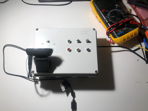
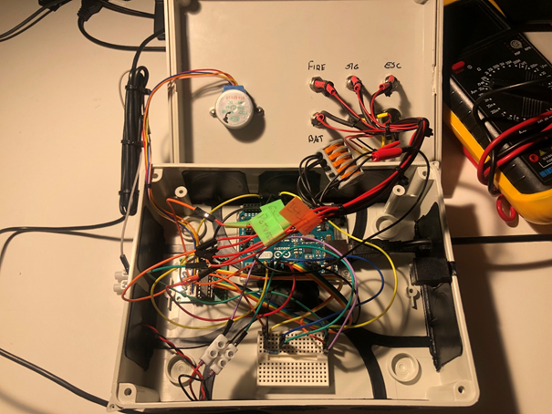
I also managed to finish the test box, or the software devkit as we like to call it. However, upon testing the finished product I noticed that some minor issues. The main problem was that the button was not working and after doing some troubleshooting I found the issue to be the button itself. The button would simply not complete the circuit when pressed. It might never have been working as it is some cheap part from China or it may have been damaged during soldering. Either way it will have to be changed out. The devkit is also missing a limit switch to zero the stepper motor.
The most important part left now regarding the electrical work is to create the necessary schematics as we already have all the required parts for our model.
Anders
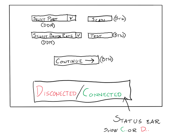
This week my focus has been directed toward crating and finalizing our GUI (Graphic User Interface) for windows. We will be using a Windows Form App deployed on the computer controlling the preliminary test setup to control the Arduino microcontroller at runtime. This is done by using the Serial Communication Port the microcontroller is connected to send a value triggering a response in the Arduino code.
What will be included in the GUI are:
- Connection panel for selecting Port where the Arduino board is connected from a drop-down menu.
- This will also include a drop-down menu for selecting the different Baude rates the microcontroller deploys, even though we could have hardcoded it to the Baude rate used in the Arduino code.
- A main panel for choosing between automatic and manual running mode.
- Two simple buttons which sends a value through the serial channel to activate either manual mode or automatic control.
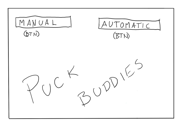
- A
manual-control panel for controlling separate functions.
- Slider for setting direction of the stepper, with a send button for sending the direction to the micro controller.
- Button for toggling the ESC (Electronic Speed Controller) on or off, this will send a signal to a relay which in turn starts the spinning of the launch mechanism.
- Button for activating the firing mechanism, this will activate the hardware used to push the Puck into the spinning wheels
- Button for toggling the battery supplying the ESC, this will also be done with a relay.
- All the above is also communicated to the microcontroller by sending a value to the microcontroller.
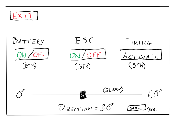
PS: My contribution to this blog post was created late Sunday afternoon of week 40 as I had a small injury while playing hockey and was hospitalized due to some unforeseen complications relating to said injury. I therefor rewrote my part at the hospital and created the drawings of the GUI as seen above to illustrate how the program at my stationary computer at home looks.
There will come actual screenshots of the program in question in week 41 when I am allowed to return home.